AWT Facility Description

The AWT employed sophisticated design features to overcome the difficulties associated with operating engines in simulated altitude conditions. These included a unique steel shell, an air scoop, a make-up air system, and unique banks of cooling coils.
Overview
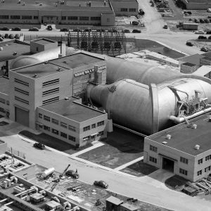
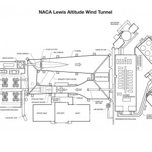
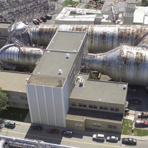
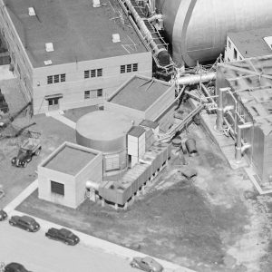
The Altitude Wind Tunnel (AWT) was among the most complex wind tunnels ever designed when it began operations in early 1944. Its state-of-the-art systems created the wind speeds, air pressure, and sub-zero atmospheric conditions experienced at high altitudes. National Advisory Committee for Aeronautics (NACA) engineers devised a number of ingenious features to overcome the difficulties associated with operating engines in simulated altitude conditions, including a robust steel shell, an air scoop, and a make-up air system. Carrier Corporation to develop an unprecedented refrigeration system to cool the massive air flow. The tunnel’s 20-foot diameter test section was large enough to operate full-size aircraft engines. The tests were conducted from a soundproof control room and complex instrumentation was employed to record test data. The tunnel test section was enclosed within the facility’s Shop and Office Building.
Documents
- Overview of AWT and SPC Facility (2009)
- AWT Historic American Engineering Report
- AWT at the AERL Talk (1943)
- Biermann Lecture on the AWT (c1947)
- AWT Facility Specifications (1957)
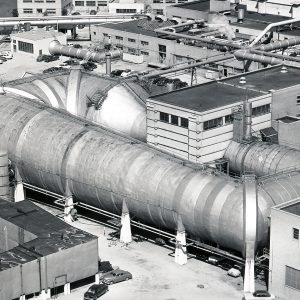
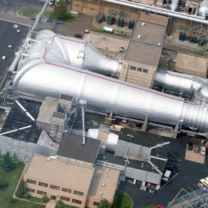
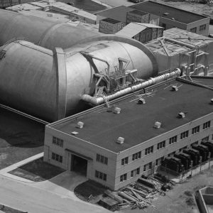
Tunnel Shell
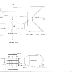
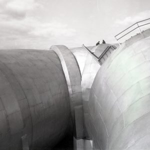
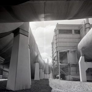
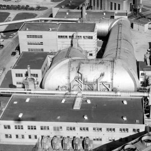
The tunnel itself was a massive rectangular structure, which for years provided one of the highest vantage points at the center. The tunnel was 263 feet long on the north and south legs and 121 feet long on the east and west sides. The larger west end of the tunnel was 51 feet in diameter throughout. The east side of the tunnel was 31 feet in diameter at the southeast corner and 27 feet in diameter at the northeast. The throat section, which connected the northwest corner to the test section, narrowed sharply from 51 to 20 feet in diameter.
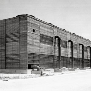
The overall shape of the AWT was similar to several other contemporary NACA wind tunnels. The AWT’s low internal pressure and temperature levels, however, required the use of new engineering concepts to design the tunnel’s steel shell.The tunnel shell consisted of two steel layers with a blanket of insulation between. The 1-inch-thick inner steel layer could withstand the external atmospheric pressure when the interior was evacuated to low pressure levels. The designers employed a T-1 steel alloy with three times the strength of normal carbon steel so that the shell could endure the low temperatures within without becoming brittle. A 4-inch layer of glass wool and steel mesh was applied over the inner tunnel shell to retain the tunnel’s low temperatures. The outer 1/8-inch-thick steel shell was then constructed over the insulation to protect the structure from the environment.
Documents
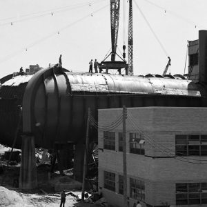
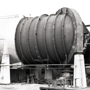
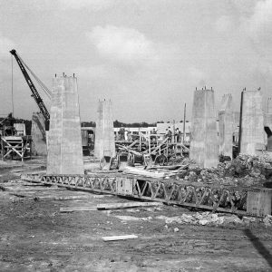
The tunnel was braced by a large elliptical support ring in each corner, the test chamber in the middle, and a series of 120 support rings which lined the tunnel at 6-foot intervals. Each of the rings were anchored to concrete and steel piers which elevated the tunnel. Unique steel rollers bore the weight of the tunnel in a way that allowed the shell to contract and expand during the tunnel’s dramatic temperature and pressure fluctuations. The rollers were placed between the concrete piers and the support ring buttresses.
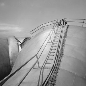
A series of steel stairs, ladders, and platforms provided access to the top of the tunnel from the second floor of the test chamber. A stairway rose from the narrow throat section to the top of 51-foot-diameter west end of the tunnel. From there, a walkway on top followed the entire tunnel circuit.
Air Flow System
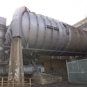
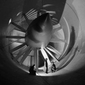
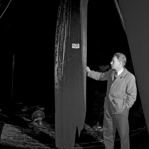
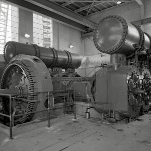
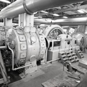
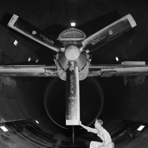
The AWT could produce wind speeds up to 500 miles per hour through its large 20-foot-diameter test section at the standard operating altitude of 30,000 feet. The average speed at lower altitudes was 345 miles per hour. A 12-bladed, 31-foot-diameter spruce wood fan near the southeast corner generated the airflow. An 18,000-horsepower General Electric (GE) induction motor located in the rear corner of the adjacent Exhauster Building rotated the fan at 410 revolutions per minute.
Flexible couplings protected the extended drive shaft, which connected the two structures, from the movement of the tunnel shell. A bronze screen secured to one of the turning vanes protected the wooden fan from flying debris and failed engine parts. Nonetheless, the blades became worn or cracked over time and required replacement. The lab installed an entire new fan assembly in 1951.
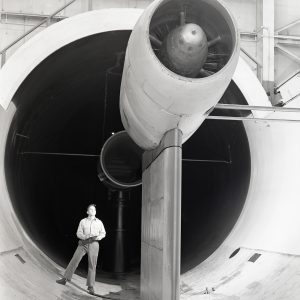
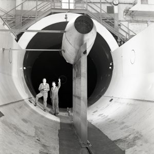
Elliptical panels of turning vanes in each corner guided and evened the airstream around the tunnel’s square corners. The tunnel contracted from a diameter of 51 feet to just 20 feet as it approached the test section. This contraction accelerated the air velocity as it passed the engine studied.
Documents
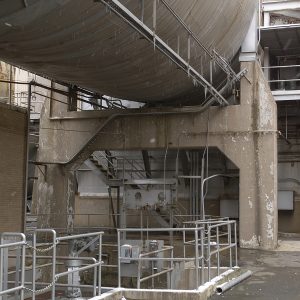
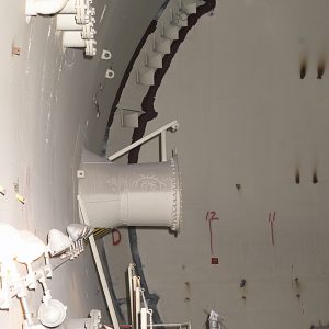
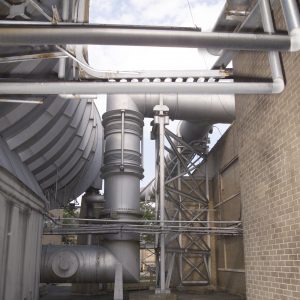
The operation of engines in the tunnel, necessitated constant purging and replenishing of the airflow to maintain the altitude conditions. A unique air scoop on a vertical support immediately downstream from the test section collected combustion byproducts exhausted by the engines. Compressors in the nearby Exhauster Building drew the vented air out of the tunnel and discharged it into the atmosphere.
A make-up air system replenished the exhausted air with cool, dry air. A large dryer located outside the tunnel’s southwest corner removed condensation from the air to prevent shocks to the tunnel’s airflow. There, atmospheric air passed over a set of cooling coils, then over beds of activated alumina in a large dryer, and finally over another set of cooling coils to reduce the temperature to the desired level.
The system introduced the processed air into the AWT through two portals in the western tunnel wall. One of the nozzles extended well into the tunnel and piped the new air directly into the test section. Later this pipe was extended and attached to the engine inlets to increase the tunnel’s capacity. The system could exchange 6,000 pounds of air per minute, which reduced airstream contamination to roughly 5 percent.
Altitude Simulation
The most complex aspect of the AWT’s operation was the simulation of altitude conditions. The massive exhauster system thinned the air and an unrivaled refrigeration system produced the low temperatures necessary for this simulation. The NACA originally designed the tunnel for temperature altitude simulation of up to 30,000 feet and pressure altitude simulation of 45,000 feet. This capacity was increased to 100,000 feet by the mid-1950s.
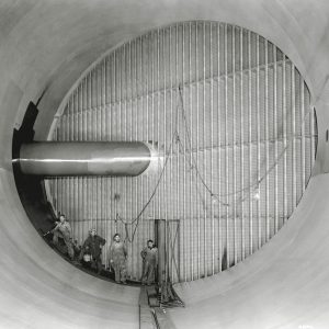
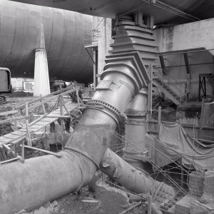
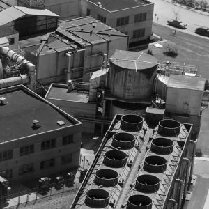
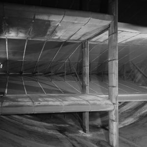
Engineers from the Carrier Corporation developed a unique refrigeration system that lowered the AWT’s interior temperature to –47°F, and, if applied to commercial purposes, could generate 10,000 tons of ice per day. Fourteen Carrier compressors in the Refrigeration Building powered the cooling system. The compressors converted the Freon 12 refrigerant into a liquid, which was then pumped into the eight identical banks of cooling coils arranged in an innovative zigzag design. This collection of 260 copper-plated coils covered the entire 51 foot width of the return leg. The Freon absorbed heat as the air flow passed through the coils and transferred it to cooling water. The cooling water flowed to an external cooling tower which the heat dissipated into the atmosphere. The system required 20,000 gallons of cooling water every minute.
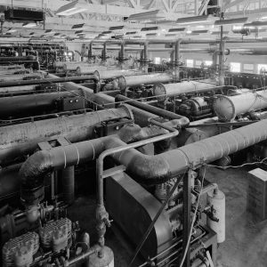
In addition to removing contaminated air through the air scoop, the exhaust system reduced the tunnel’s air pressure to create the thin atmosphere found at high altitudes. The Exhauster Building, directly to the east of the tunnel, housed four 1,750-horsepower exhausters which pumped 2/3 of the air out of the tunnel and expelled it into the atmosphere. Roots-Connersville centrifugal compressors in the Engine Research Building’s basement removed the remaining air. The original configuration could simulate altitudes up to 45,000 feet. The Exhauster Building was expanded in 1951 to house more powerful compressors, and the system was soon linked to exhaust systems at other test facilities.
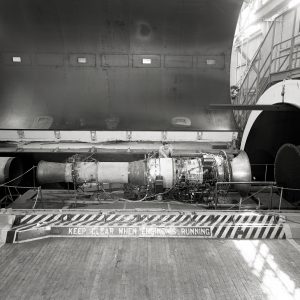
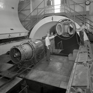
Test Chamber
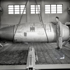
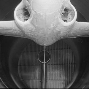
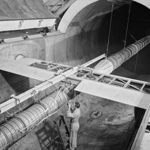
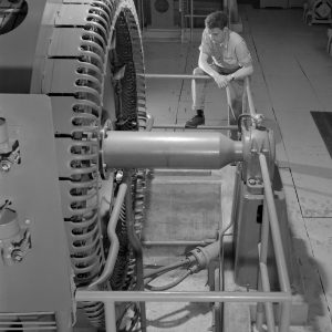
The size of the AWT’s 20-foot-diameter and 40-foot-long test section was driven by the desire to test full-scale engines up to 3000-horsepower. This was larger than the piston engines in use in the early-1940s. A large overhead crane lifted the engines through the high-bay and the second-story test chamber before being lowering them into the test section. Technicians then spent days or weeks hooking up the supply lines and instrumentation. The engines were generally mounted on wing spans that stretched across the test section. The wing tips attached to the balance frame’s trunnions which could adjust the angle of attack. The balance frame included six measurement devices that recorded data and controlled the engine.
Documents
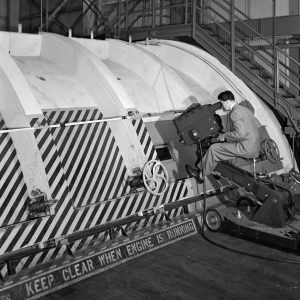
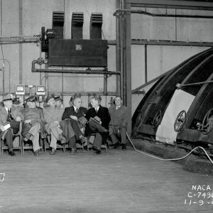
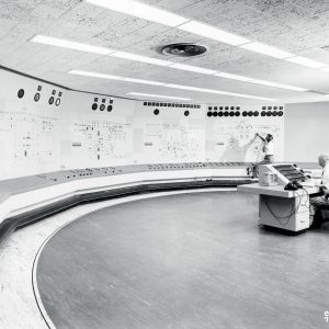
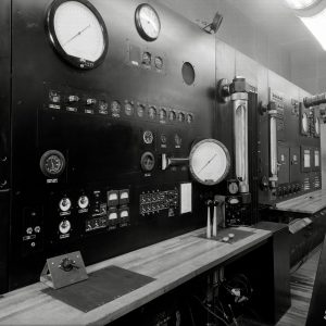
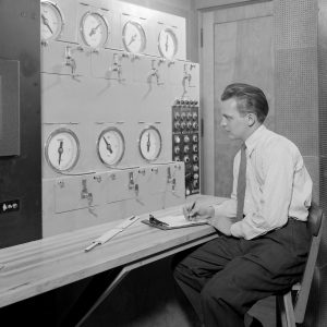
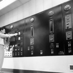
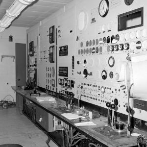
Staff operated the tunnel and the experimental engine from a soundproof control room next to the test section. The test operators worked with assistants in the Exhauster Building and Refrigeration Building to manage the large systems. Although the configuration of the control panels changed frequently, the room’s principal wall contained the make-up air, drive fan, and engine controls. It also included two sets of pneumatic levers that operated different facets of the engine. The panels on the opposite wall managed the combustion, refrigerated and cooling air, and the exhauster systems.
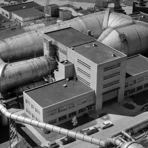
The AWT’s test section, control room, and balance chamber were located in a three-story test chamber in the rear of the Shop and Office Building. The control room, fan room, and manometer boards were located on the mezzanine level next to the test section. The upper level was a large open space, approximately 50 feet high, with the test section sunken up to its midpoint in the floor. This main level contained a large, wooden viewing platform with stairs built so that people could get from one side of the test section to the other. A mechanical pulley system raised and lowered the tunnel’s large clamshell lid into place. Hand-turned locks accessible from the viewing platform sealed the lid. Viewing windows in the lid permitted the filming and visual inspection of the tests.