Turbine Sites
Turbines, which rotate drive shafts at specific speeds, are a critical element of turbopump operation and efficiency. The turbine consists of an inlet, several stages with wheels and nozzles, and the drive shaft. Liquid rocket engines used a turboexpander to convert a quantity of the liquid hydrogen to a gas which expands and rotates the turbine wheel. This starts the turbopump which sends fuel to the combustion chamber to start the engine. The Rocket Systems Area’s Hydraulics Laboratory (F Site) and Pump and Turbine Facility (G Site) were designed to test turbines for liquid rocket engines.
F Site – Hydraulics Laboratory
F Site, also referred to as the Hydrogen Flow Facility, was designed to study the flow conditions of cryogenic fluids as they passed through an experimental turbopump. Researchers also used the facility to study a liquid-hydrogen heat exchanger for nuclear rockets.
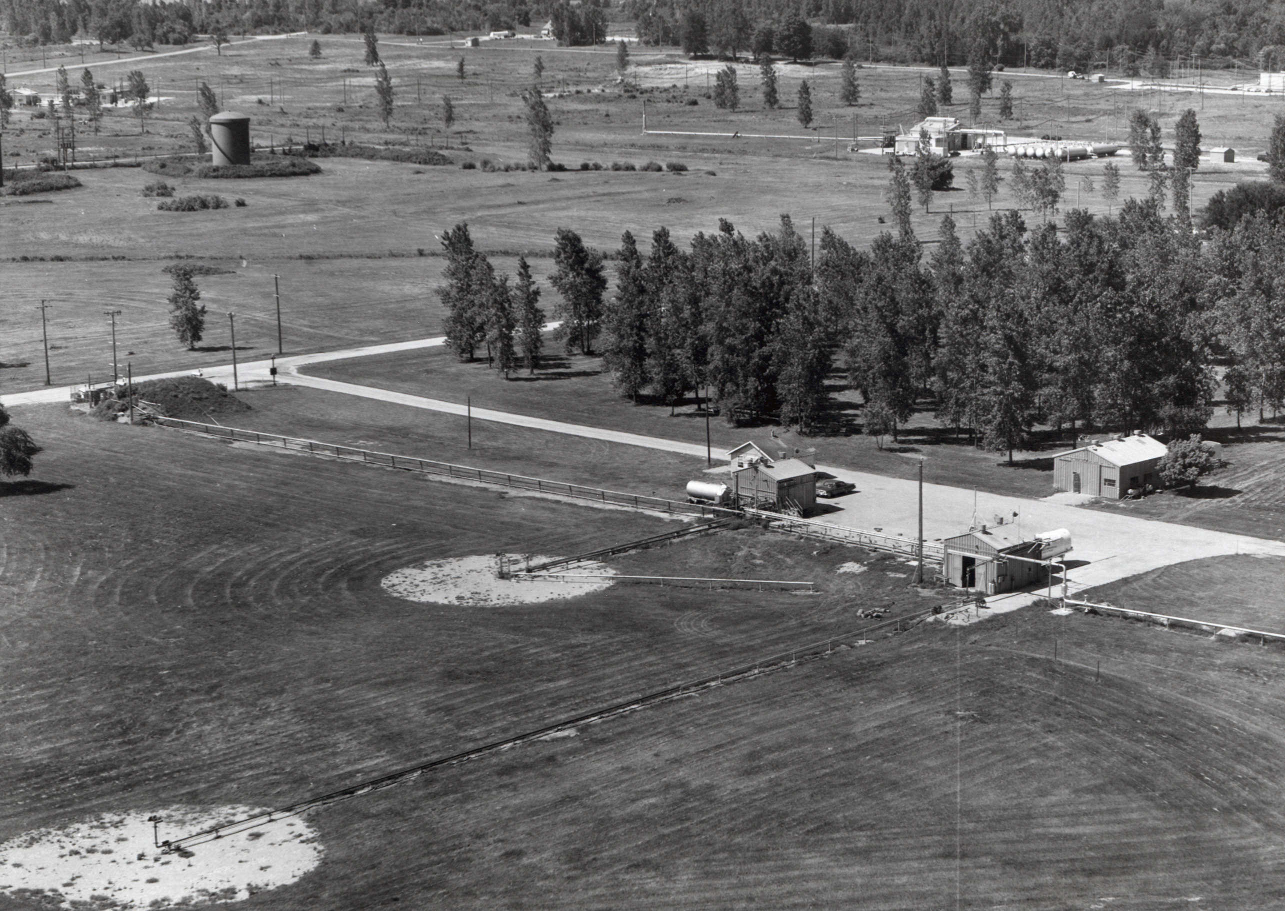
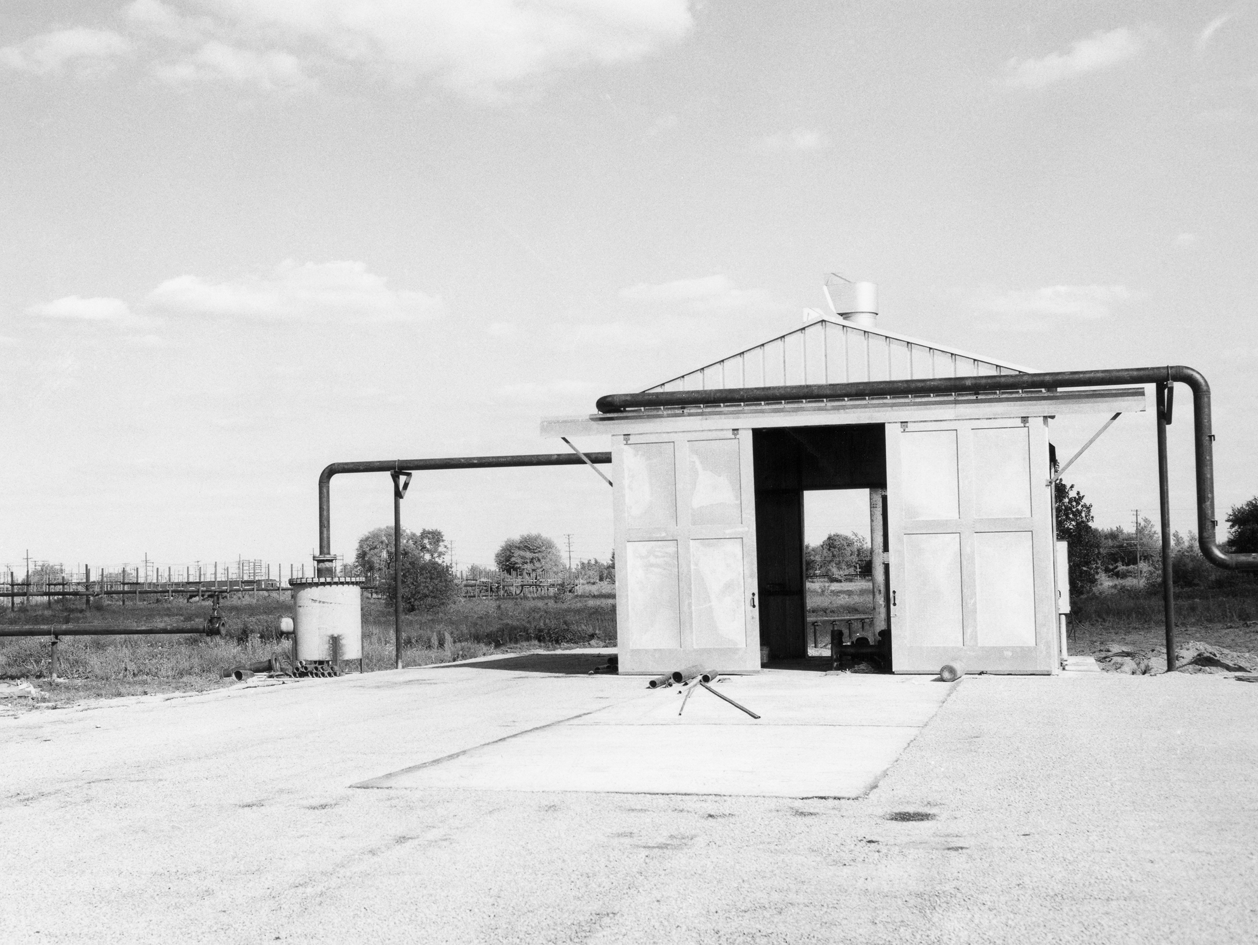
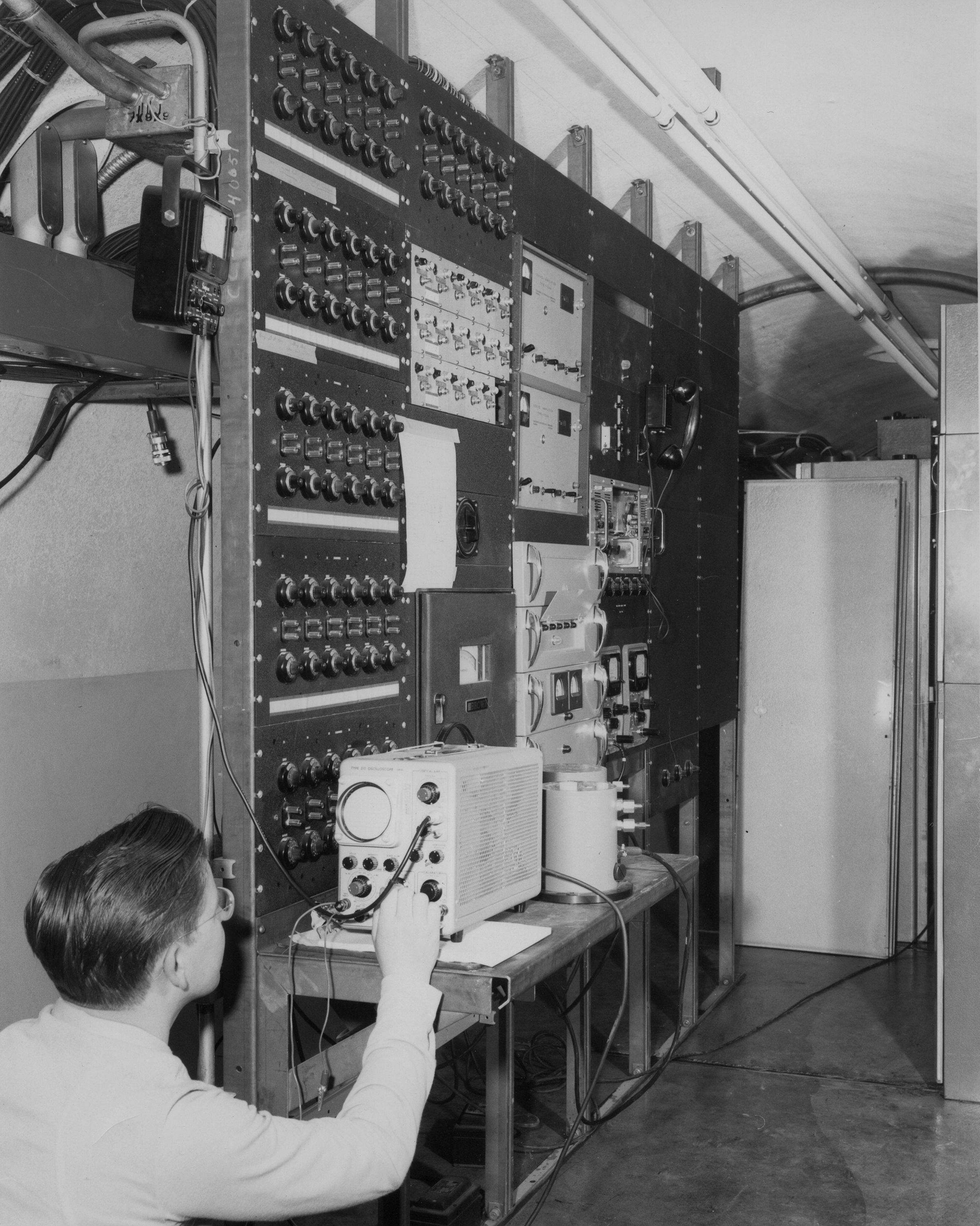
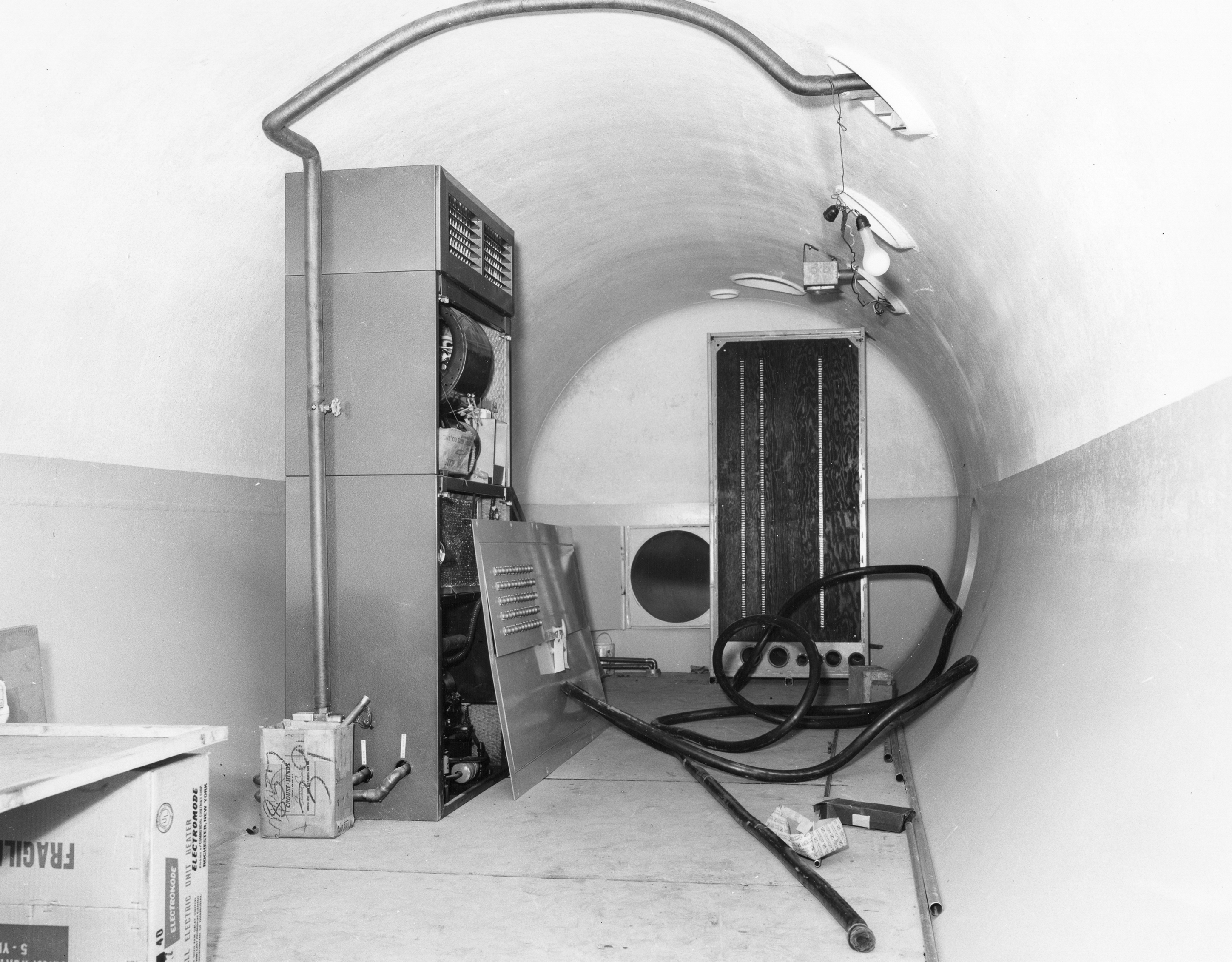
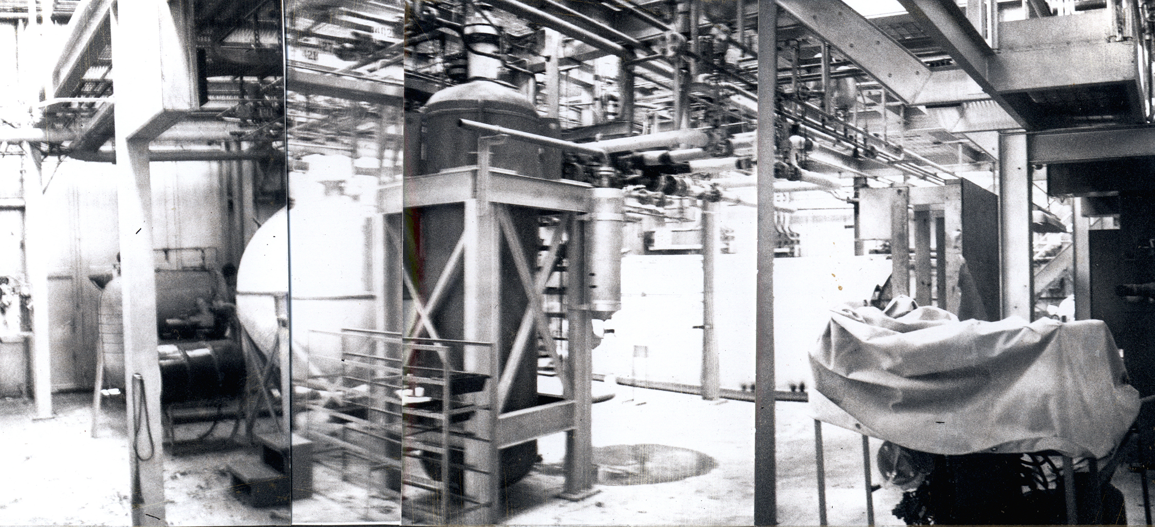
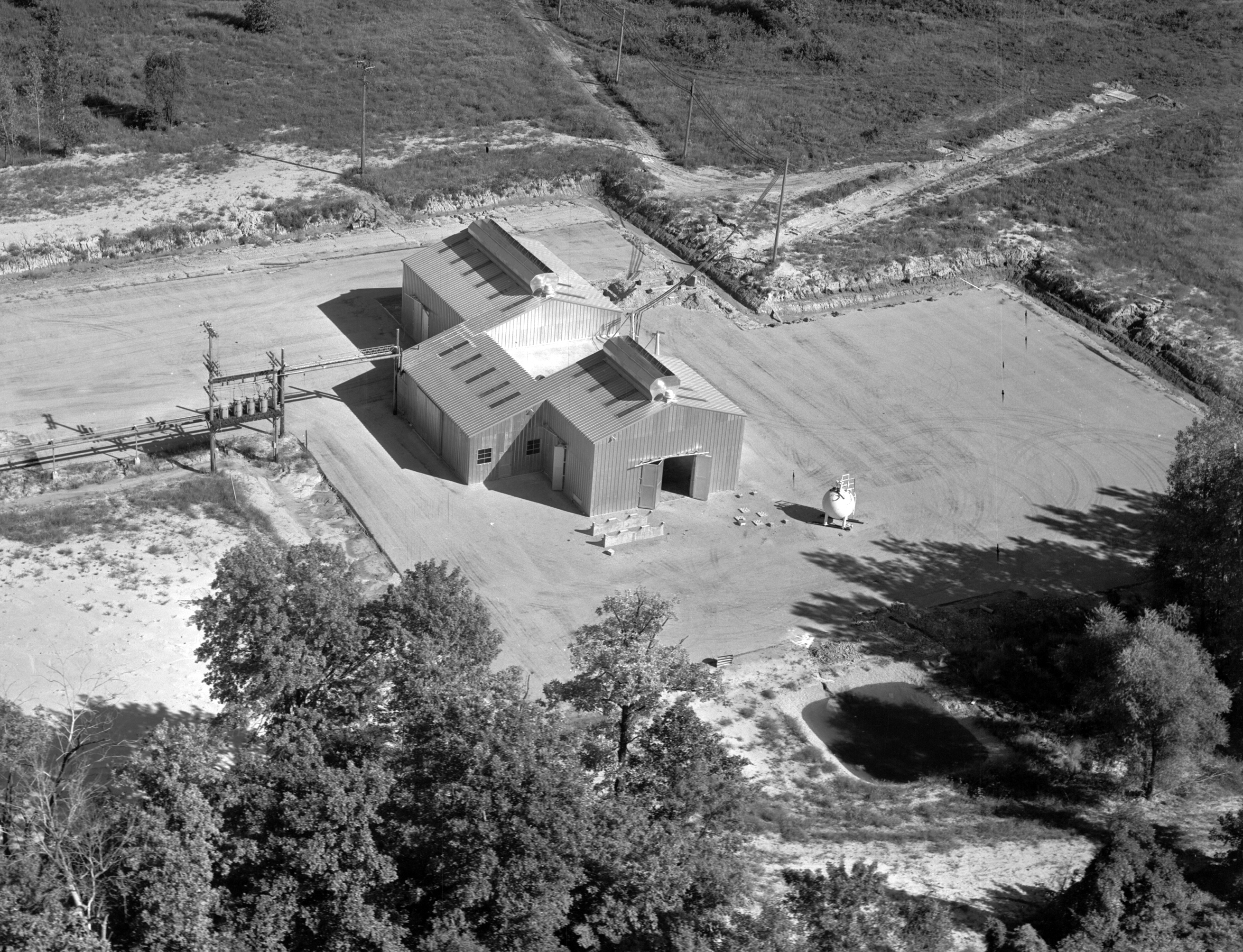
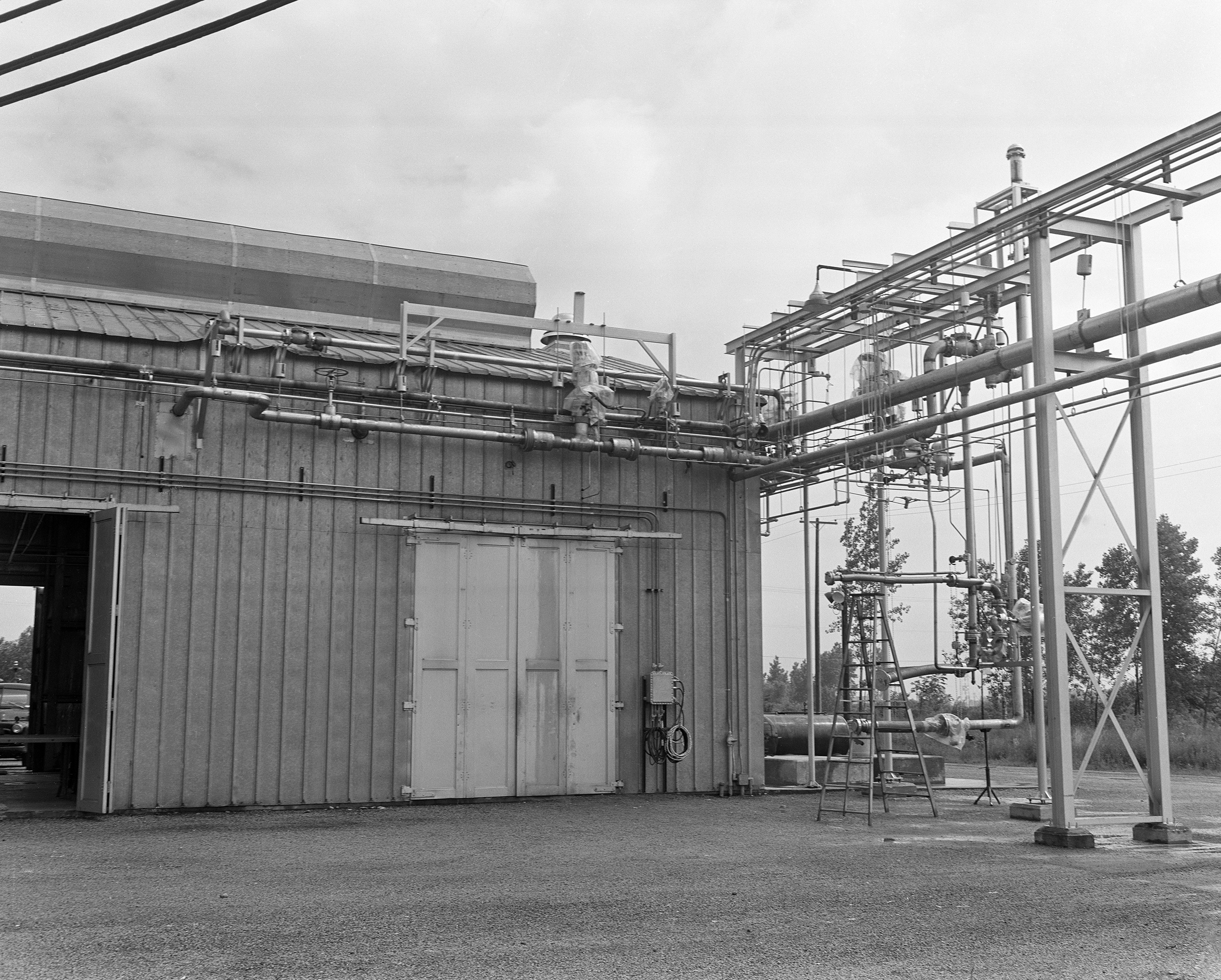
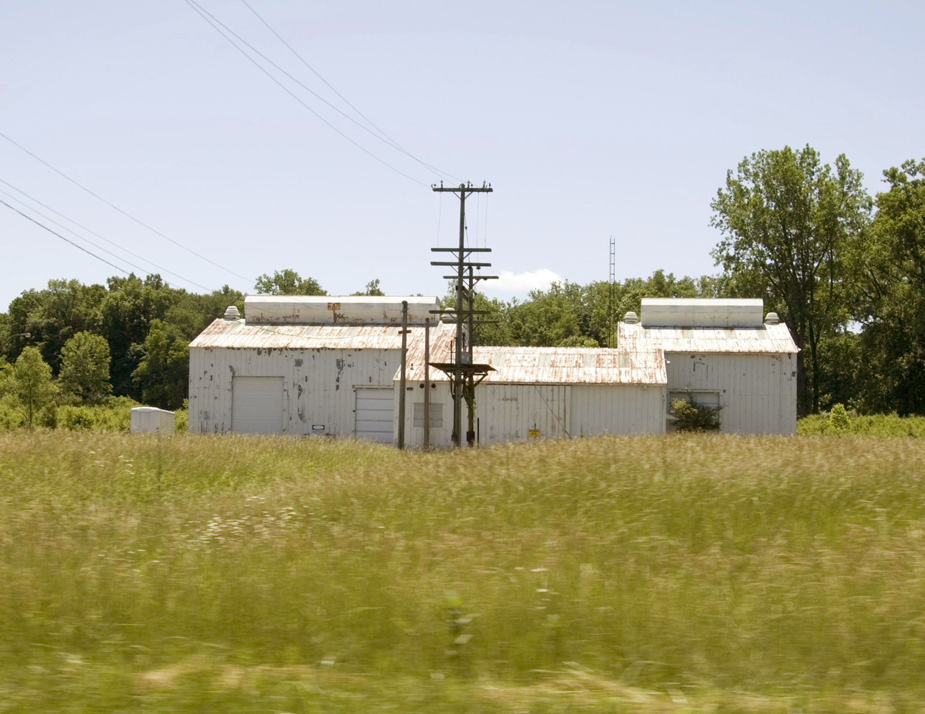
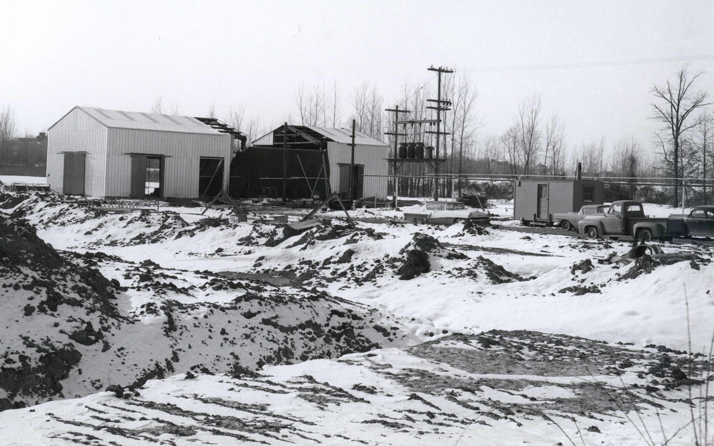
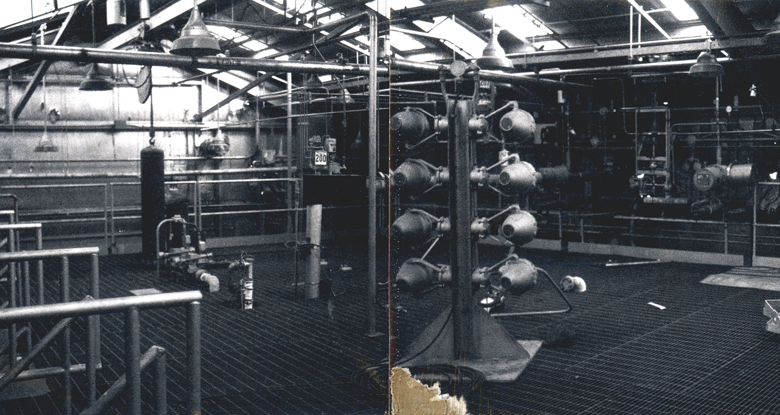
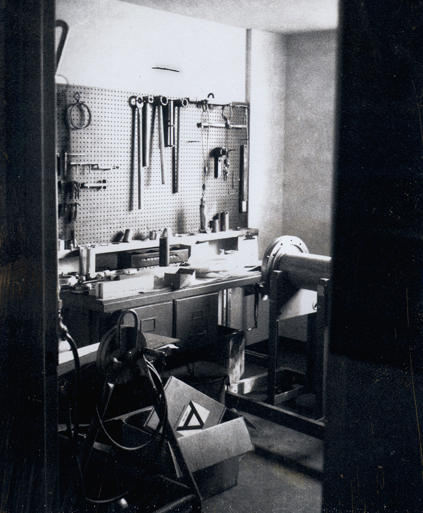
Physical Description: F Site, located on Fox Road, was the westernmost Rocket Systems Area facility. The primary structure was a rectangular Butler Building that had a hydrogen test area in the west section, another test area was to the east, and a third test area on the mezzanine level. The Instrument Room, the Control Room, and the Electric Mechanical Room were located between the two test sections. A rectangular shop area abutted against the north side of the structure. F Site contained a liquid-hydrogen storage vessel and a catch basin with the experimental flow hardware set up in between. A small pump house was located to the north of the structure, and a hydrogen burnoff line was located to the south.
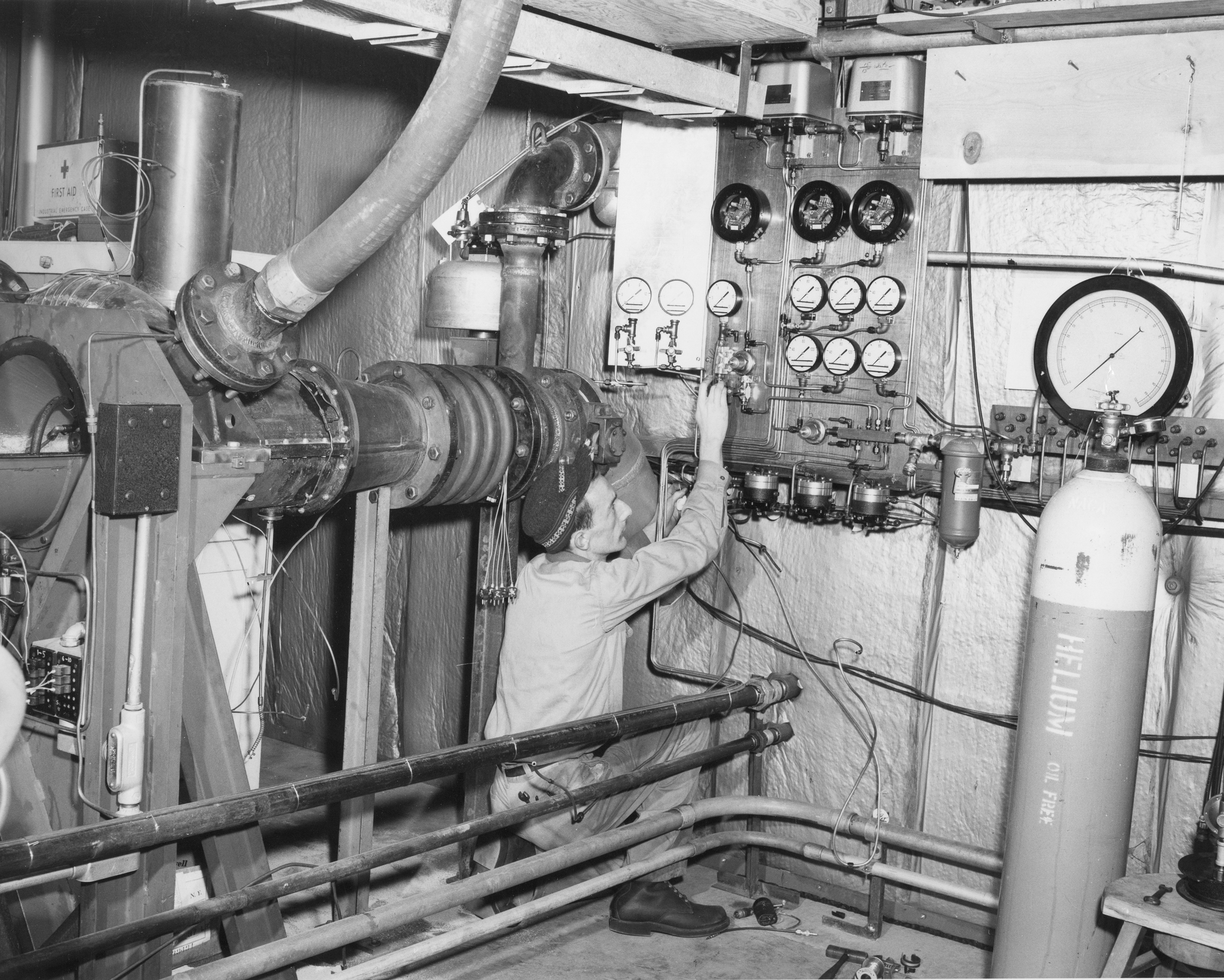
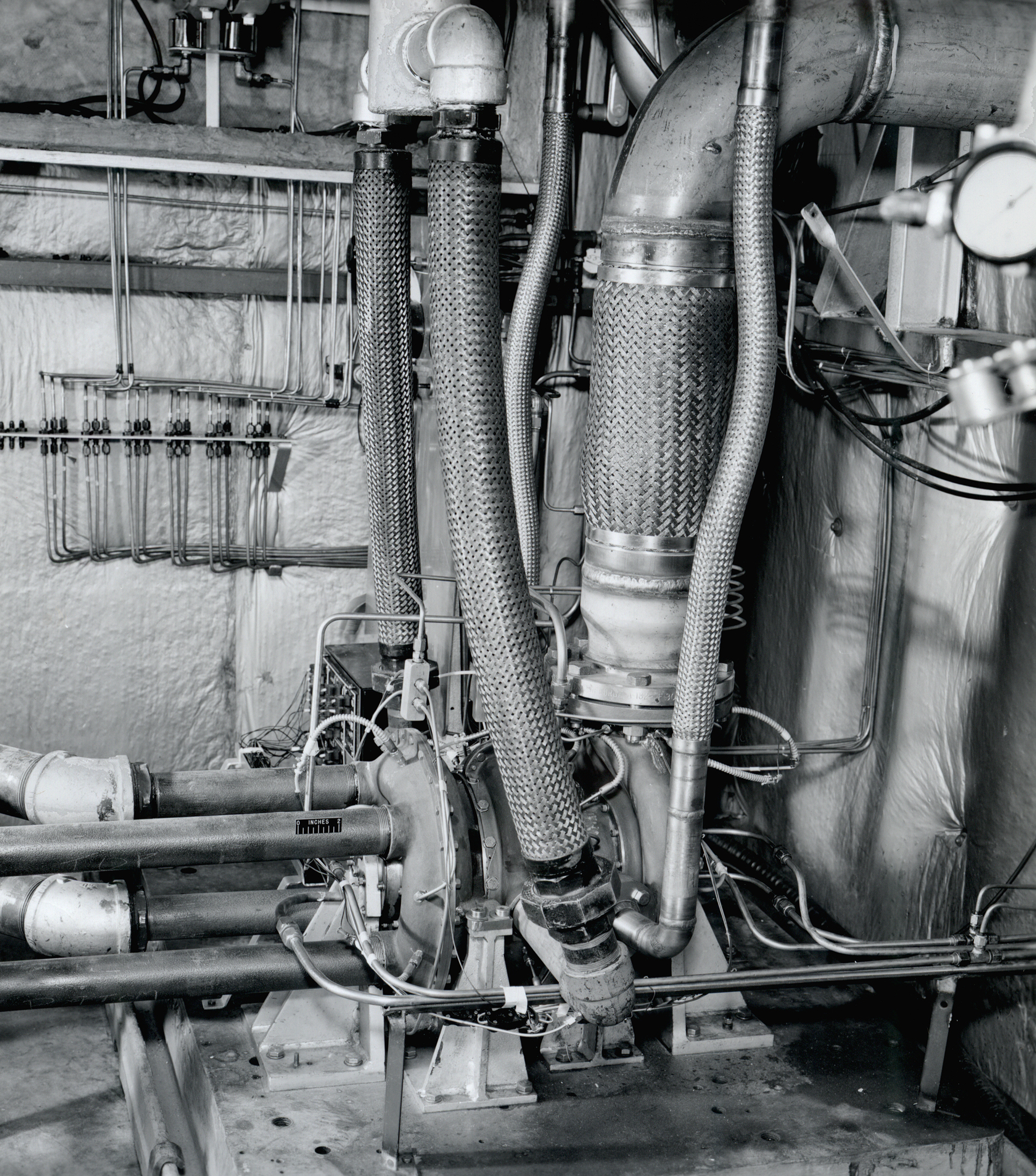
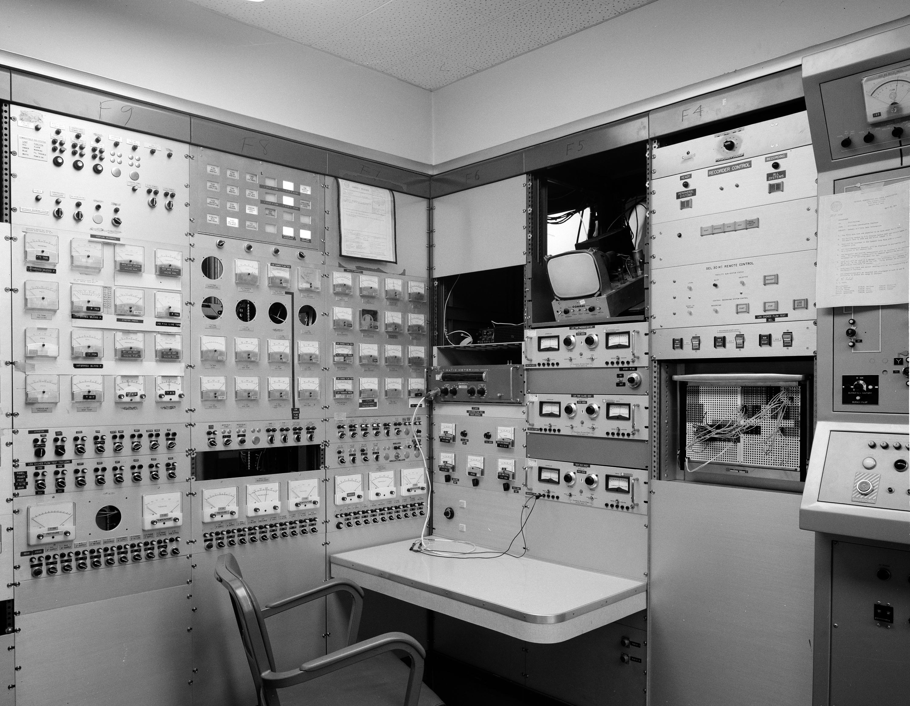
Operation: The experimental component, usually a turbopump, was installed in the test loop between the two hydrogen tanks. The operator pressurized the propellant run tank and stabilized the system. The valves were then released as the pump transferred the fluid from one tank to the other. The staff could modify the fluid temperature during the test by introducing ambient gas into the liquid. The operators conducted the tests from the H Control Building.
Tests: Researchers used F Site to analyze a triangular hydrogen heat exchanger for a nuclear rocket, to cold shock a Centaur 5–C tank, and to study the choked flow of liquid oxygen.
- 1963–66 Hydrogen-water heat exchanger for nuclear rocket
- 1963–64 External insulation system for Centaur tank
- 1968 Centaur tank cold shock
- 1974 Liquid-oxygen choked flow
Documents
- F Site Description and Floor Plans
- F Site Status Reports (1963-74)
- Heat Transfer of Water-to-Hydrogen Heat Exchanger (1969)
- Two-Phase Choked Flow of Oxygen and Nitrogen (1976)

G Site—The Pump and Turbine Facility (Pilot Plant)
The Pump and Turbine Facility, better known as the Pilot Plant, was designed to test models of Lewis-designed rocket pumps and turbines with cryogenic propellants before the designs were provided to manufacturers for production.
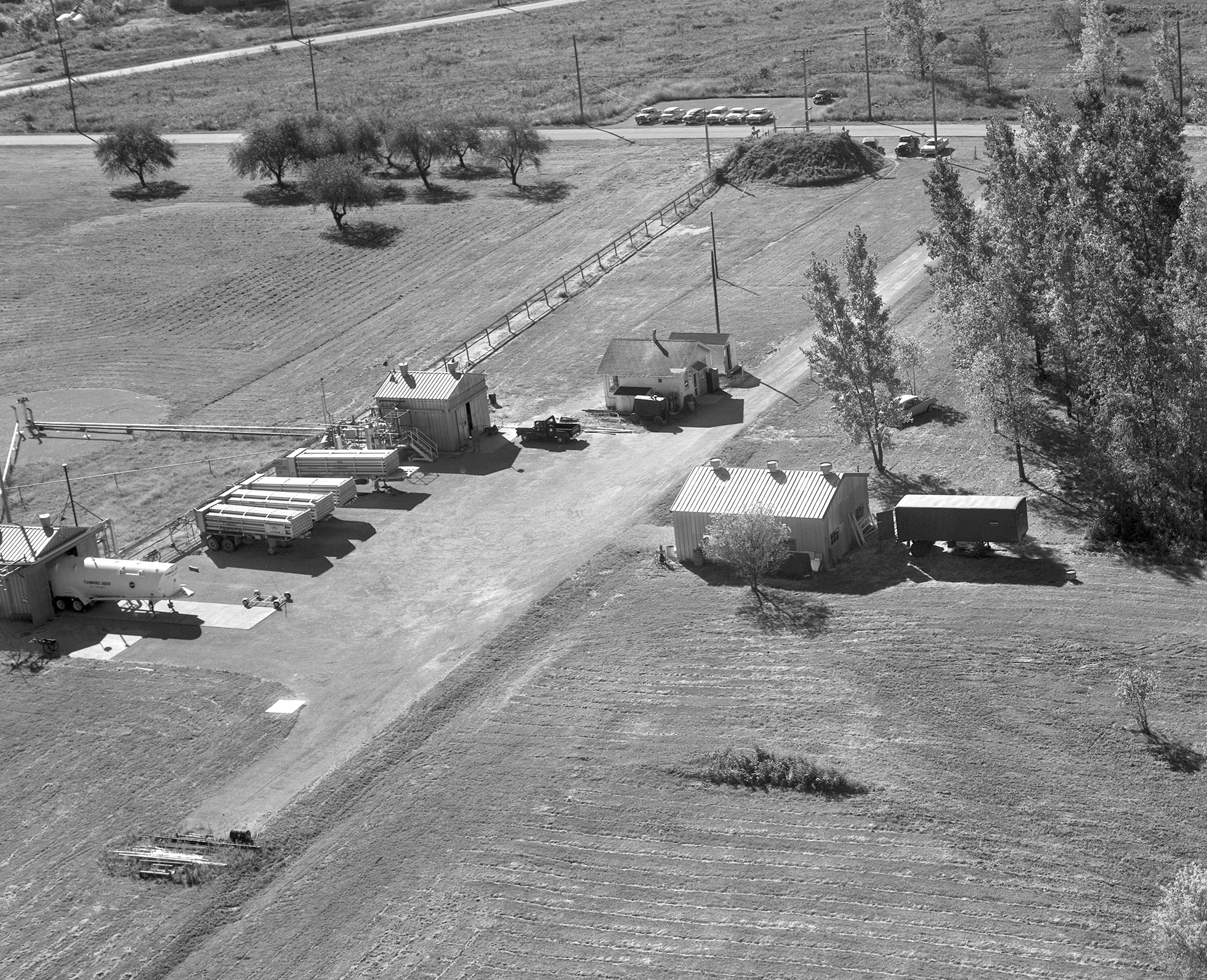
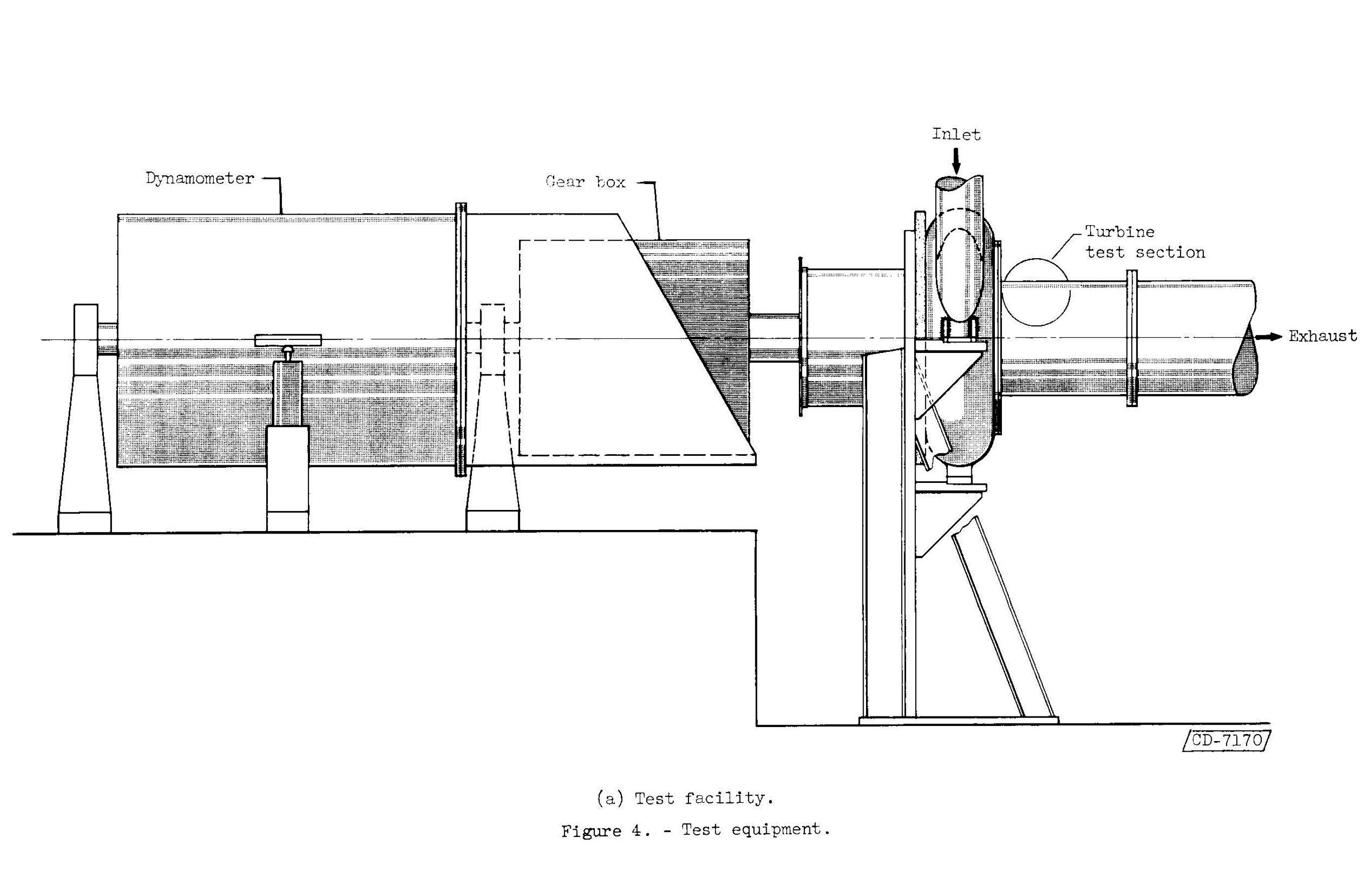
Physical Description: The Pilot Plant was located on Fox Road in the northcentral portion of the Rocket Systems Area. The site had two test facilities—the Liquid Hydrogen Pump and the Turbine Test Facility—located 350 feet north from its control and instrument rooms. These rooms were repurposed 9-ft-diameter steel tanks from the Plum Brook Ordnance Works (PBOW) that were covered with an earthen mound. The Turbine Test Facility contained a test section for the experimental turbines, a pressure-controlled inlet duct system, and an exhaust duct that vented directly to the atmosphere. The test equipment included the turbine, housing, and the dynamotor. There was a shop building to the east of the two test facilities and a pump house to the south.
Operation: The staff installed the model pump or turbine in the corresponding test building, connected a roadable hydrogen Dewar to the equipment, and stabilized the pressure and temperature levels. The pump circulated the gaseous hydrogen or nitrogen propellant from the Dewar and back into a catch basin. The operator, located in the onsite underground control room, could control the inlet flow and exhaust with valves in the test apparatus. Strain gauges measured the torque, and a tachometer measured the turbine speed.
Tests: Researchers used G Site’s Turbine Test Facility to test the performance of experimental axial-flow turbines for nuclear rocket engines and to test liquid-hydrogen-cooled bearings. The Liquid Hydrogen Pump was used to test small-scale axial-flow turbopumps.
Liquid Hydrogen Pump
- 1961 15,000-rpm hydrogen axial-flow pumps
- 1964 Small-scale axial-flow hydrogen pump
Turbine Test Facility
- 1961 Three-stage Nuclear Engine for Rocket Vehicle Application (NERVA) turbine and six-stage Hy-Nut Turbine
- 1963–64 Three-stage axial-flow hydrogen pump for hydrogen-cooled bearings
Documents