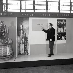
RETF Buildings and Systems
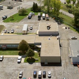
The Rocket Engine Test Facility (RETF) originally included two major components: a control center in Building 100, and a test cell in Building 202. There was also an observation blockhouse that protected the researchers while they observed the tests, fuel storage areas, and a waste water treatment system. The Propellant Transfer and Storage Facility, was added between 1962 and 1965, and the Cryogenic Vaporizer was built in 1968.
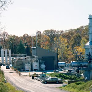
When the RETF was completed in 1957, it was the largest test facility in the U.S. that was capable of handling liquid hydrogen and other high-energy liquid fuels. Because of the experimental nature of the testing that took place at RETF, the facility was located on 10 acres of land a safe distance away from the other facilities at NASA Lewis Research Center. This area was referred to as the South 40.
Documents
- RETF Specifications (1954)
- RETF Facility Articles (1979-89)
- RETF Facility Modifications (1952-68)
- RETF Complex Description (1984)
- RETF Technical Resume (c1966)
- RETF Key Facility Report (c1981)
- RETF Significant Assets List (1997)
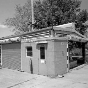
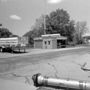
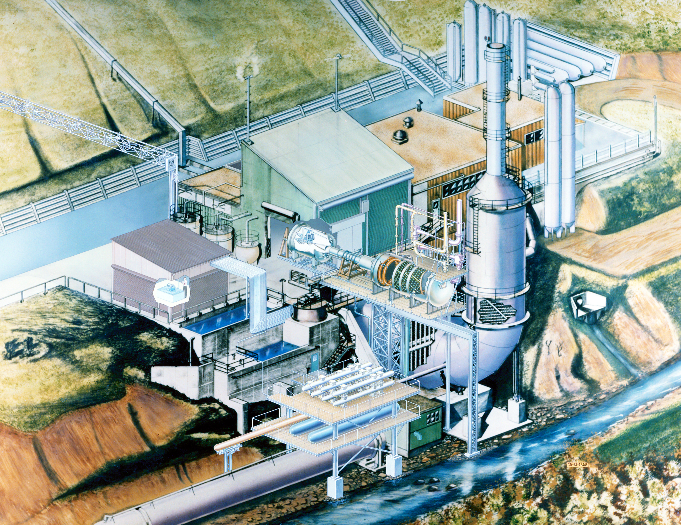
Rocket Engine Test Cell
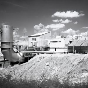
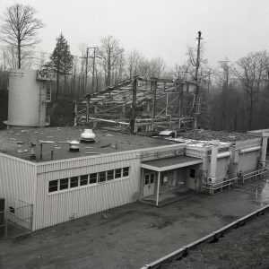
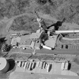
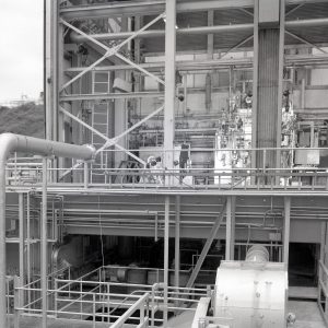
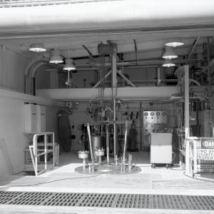
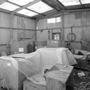
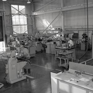
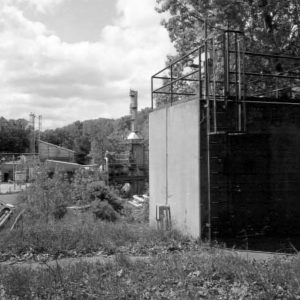
The Rocket Engine Test Cell (Building 202) originally housed a test cell, a propellant supply system, a waste treatment system, and a distinctive scrubber system that removed combustion waste products from the exhaust stream and muted the noise of rocket firing. There was a small shop adjacent to the test cell where personnel assembled engines and installed instruments to measure test data. The building also contained an observation room, office, tool crib, locker room, and bay with a boiler and an electrical distribution cabinet. The structure was cleverly situated in a valley so that any explosions were directed toward the opposing wall of the gorge, which formed an ideal barrier to protect the area from blasts.
Documents
- RETF Overview Charts (2003)
- Test Cell Building Drawings (2003)
- Test Cell Building HAER Report (2003)
Test Cell
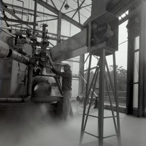
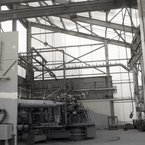
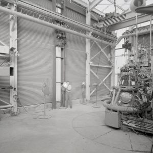
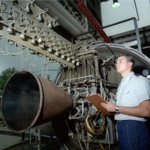
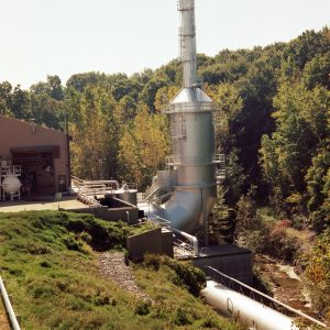
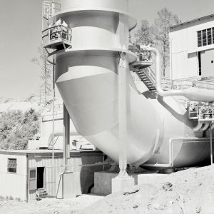
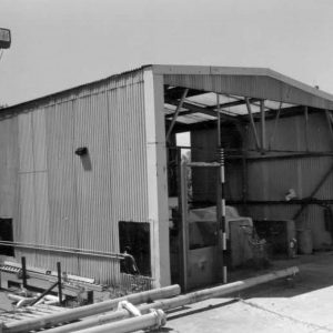
Test Cell: Building 202’s 25-foot high test cell was a modular framed structure primarily supported by upright steel I-beams. The walls and roof of the structural frame were sheathed in corrugated Transite sheets that easily blew out to relieve pressure if an explosion occurred during a test. The cell was equipped with large doors and blast shutters that could open during testing.
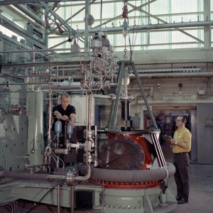
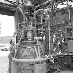
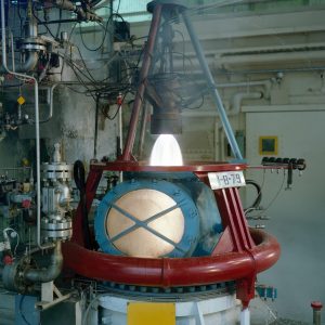
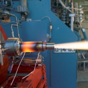
The vertical test stand (Test Stand A) located at the center of the test cell was built to accommodate the firing of rocket engines with a maximum thrust of 20,000 pounds for up to three minutes, but the overall system was designed to handle engines exerting up to 100,000 pounds of thrust. Most engines tested at the RETF had 4.8-inch chambers with 2.62-inch throats, or 10-inch chambers with 7.6-inch throats. The test engine was supported on a thrust stand and exhausted directly downwards into the inlet to the scrubber.
The supporting frame for the engine was instrumented with strain gauges, pressure sensors, load cells, and thermocouples that measured the engine thrust and other data. These data were sent to the adjacent observation room with equipment to relay data to the control room. A periscope-like mirror system allowed the observer to watch a test directly from a safe location. The engineer in the observation room could also immediately terminate a test by pressing an “abort” button related to a programmable logic controller.
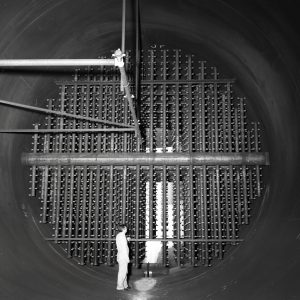
In 1984, Building 202 was modified to add capabilities for evaluating rocket nozzles with ratiosup to 1,000-to-1 on small, low-thrust engines. The new test stand (Test Stand B) simulated the vacuum of space through a large vacuum tank that housed the engine during active testing. Engines were mounted horizontally in this test stand, while the engine exhaust was directed through a water-cooled diffuser and inter-cooler, and into the existing scrubber/silencer. In 1991 Test Stand C was added for testing seal materials and designs for liquid-oxygen pumps and other components.
Documents
Scrubber
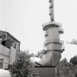
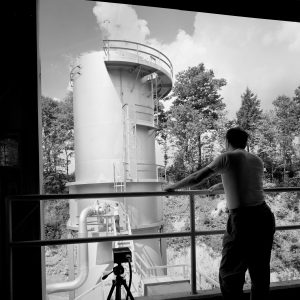
The exhaust from a chemical rocket-engine test needed to be cleaned before it entered the atmosphere. Environmental precautions were essential because the facility was located in a densely populated urban area. The RETF used an innovative exhaust scrubber that removed toxic byproducts from the exhaust and muffled the roar of the firing test engine. The large J-shaped (25 feet-wide by 100 feet-long) scrubber was equipped with multiple water spray nozzles that cooled the exhaust stream, dissolved soluble matter, and captured solids.
The rocket engine’s hot gases entered the scrubber through a narrow opening in the test cell. These gases, with temperatures up to 6,000°F, traveled at velocities of 9,000 to 12,000 feet per second. The gases were trapped in the water spray coming from the aerosol nozzles. The exhaust stream then entered the large scrubber tank at a speed of 25 feet per se.
Much of the exhaust was converted to steam and escaped through the vertical portion of the scrubber at a velocity of approximately 20 feet per second and a temperature of 160°F. Several burners on top of the scrubber ignited any hydrogen or other fuel not consumed by the engine. These burners prevented unburned fuel from building to explosive levels inside the scrubber.
Documents
Water Supply and Treatment
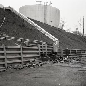
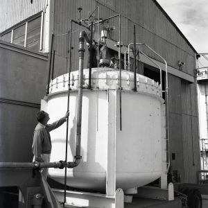
Water for the scrubber was fed by gravity from the 500,000-gallon tank located on the hill above the test cell. This reservoir supplied the water needed during a RETF test run at rates as high as 50,000 gallons per minute.
Water, condensed steam, and combustion by-products trapped by the scrubber drained into a detention tank with a capacity of 20,000 gallons. Wastewater remained in this tank until the end of the day’s test program, when it was pumped into a neutralizing tank. Chemical technicians analyzed the wastewater and determined the quantity and type of additive needed to neutralize acidity or alkalinity. After treatment, the water was retested and then pumped to a holding tank. The treated water was then pumped to the municipal wastewater treatment plant, and solid wastes were sent to a stable landfill.
Documents
Fuel Supply
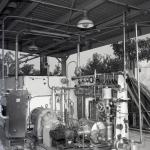
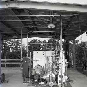
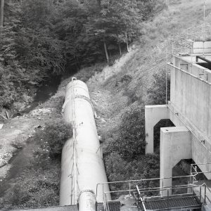
The availability of an adequate fuel and oxidizer supply that could be forced into the test engine at a controlled rate was critical to successful engine testing. Hazardous reactants also had to be kept isolated before being pumped into the rocket engine. Storage areas for fuels were located on the hillside east of Building 202. Reinforced concrete fuel and oxidant pits for storing fuels were also located adjacent to, but 26 feetbelow the test cell. The chemicals were transferred from tankers or Dewars above into the cylindrical tanks suspended in the pits.
Oxygen flowed through a pipe that was jacketed in a liquid nitrogen bath, and ran to the tanks in the oxidizer pit. The tanks in the oxidizer pit were encased in outer tanks that also contained a liquid nitrogen bath. These liquid nitrogen baths maintained the oxygen in a liquid state. The liquid oxygen was then forced from the tanks and into the test engine by displacement from helium gas under pressure. The system of using gas pressure to move reactants to the engine eliminated the need for expensive turbo pumps.
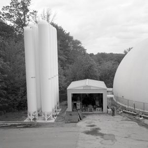
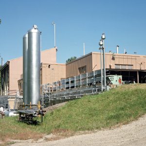
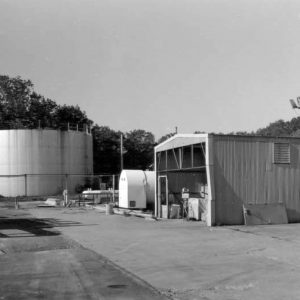
Propellant Transfer and Storage Area
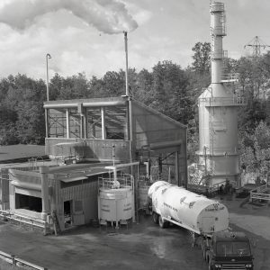
The Helium Gasification and Pressurizing Facility (Building 205) housed the compressor and automated control system that pressurized helium gas used to pump liquid oxygen from the oxidation pit to the test cell. The lightly constructed shed was built circa 1962‒1965 approximately 170 feet north-northeast of the RETF test cell. When the RETF complex was built, commercially available mechanical pumps for handling cryogenic fluids were not ideally designed for forcing liquid oxygen at high flow rates into test engines. To overcome the problems inherent in directly pumping liquid oxygen, the designers developed a unique indirect pumping system that used pressurized gaseous helium to force liquid oxygen through the piping system.
Documents
- Propellant and Gas Supply Systems Specs (1956)
- Propellant Transfer and Storage Chart (2003)
- Propellant Transfer and Storage HAER Report (2003)
- Rocket Reactant Flow Chart (2003)
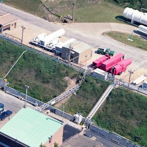
Rocket Operations Building
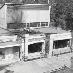
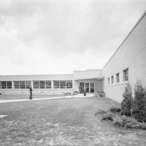
The Rocket Operations Building (Building 100) was built 1,600 feet north of the actual test stand to provide a safe location where engineers could run the tests. The longer leg of the T-shaped building housed offices while the shorter perpendicular section contained a high bay with laboratories in one wing and the RETF control room in the other.
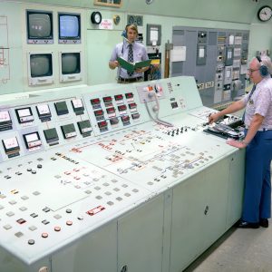
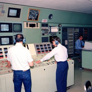
The northernmost wing of the building housed the central control room where engineers ran and monitored rocket engine tests. The room was also used to control the transfer and pressurization of the fuels and oxidizers used during the engine tests. Equipment in this space also detected, monitored, and recorded engine performance during tests. The main control and instrument consoles were centrally located and surrounded by model or control boards that showed the operating status of the major valves, pumps, motors, and actuators. The control console and model boards had schematic representations of the facility’s systems. The control room underwent several reconfigurations since 1957. Changing technology and the addition of a high-altitude rocket test stand and a turbo pump test stand required the addition of new control and recording equipment.
The operation, sensing, and recording of engine tests were initially done using electro-mechanical devices. During this period, run data were analyzed and reduced by employees who were referred to as “computers” using slide rules and manual computation. This work was gradually supplanted by mainframe computers. In the late 1970s, programmable logic controllers replaced the earlier electro-mechanical devices used in the RETF control system. A programmer calibrated the logic controllers to operate the valves and actuators controlling the fuel, oxidant, and ignition sequence according to a predetermined time schedule. The staff could manually override the system if necessary.
Originally, the performance data of a run were recorded on magnetic tape or paper-based records. The data was reduced using thermal paper linear recorders, multicolor pen recorders, or Visicorders. In the 1980s, RETF personnel reduced raw data using Lewis-developed TRADAR or CADDE programs. These data were then sent for further processing in the Cray and mainframe computers in the Research Analysis Center.
Documents
Observation Blockhouse
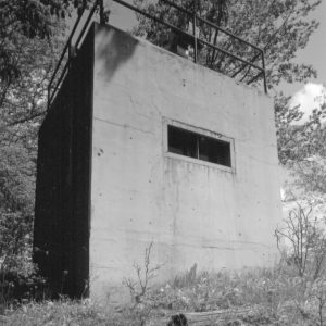
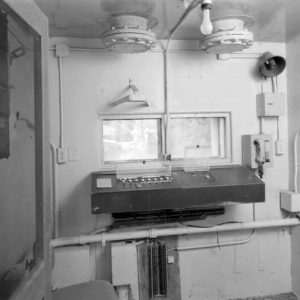
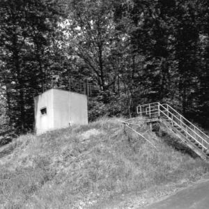
The observation blockhouse provided technicians and engineers a safe location to directly observe RETF engine firings to supplement instrument readings. The small concrete blockhouse, located approximately 294 feet north of the test stand, protected the observers from flying debris in case of catastrophic engine failure. The blockhouse was equipped with an intercom system, emergency communications, a telephone system, and the ability to remotely shut down the test. As sensors, instrumentation, and computerized data reduction became more sophisticated, the information that could be provided by observers in a protected area became less significant and the blockhouse fell into increasing disuse.
Documents
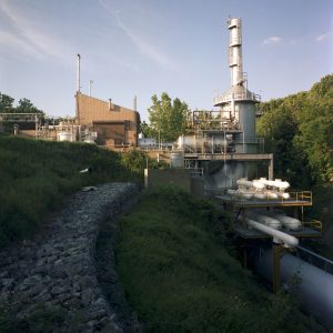
Cryogenic Vaporizer Facility
The Cryogenic Vaporizer Facility (Building 206), constructed in 1968, housed a liquid nitrogen vaporizer and gaseous nitrogen compressor. An isolated concrete-block control room in the southwest corner features a small window that allowed personnel to monitor the machinery and a switchboard that controlled motors and fans. The inert, nonflammable nitrogen gas powered the RETF’s pneumatic actuators that opened and closed valves, pressurized the fire suppression system, and later, created the vacuum for Test Stand B. Liquid nitrogen was first fed through a pump/compressor. The highly pressurized fluid then flowed through a network of pipes to the vaporizer. Fans pulled ambient air across the exterior surface of the pipes. The liquid nitrogen in the pipes warmed and boiled, forming high-pressure nitrogen gas. This gas was then piped throughout the RETF for use.
Documents