Support Buildings

The AWT relied upon equipment in several external buildings to create the facility’s altitude environment.
Overview
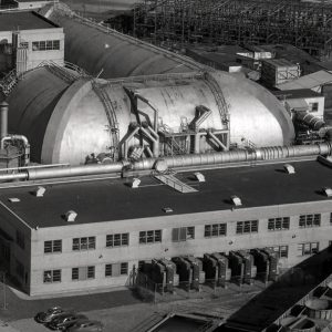
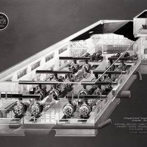
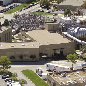
The Altitude Wind Tunnel (AWT) facility comprised a number of components, which allowed the tunnel to study aircraft engines in an altitude environment. The Shop and Office Building contained the test section, control room, large shop area, three-story high-bay, and two-floor office wing. The Refrigeration Building housed the Carrier Corporation’s powerful cooling system. The Exhauster Building contained the compressors, which reduced the air pressure within the tunnel and the motor that rotated the tunnel’s drive fan. The AWT infrastructure was powerful enough to also run several small supersonic wind tunnels, cool the Icing Research Tunnel, and support engine tests in other facilities.
Documents
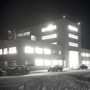
Shop and Office Building
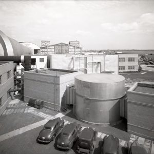
The Shop and Office Building was the heart of the AWT facility. The Sam W. Emerson Company constructed building in the same architectural style as the other original buildings at the laboratory. The eastern wing of the T-shaped building consisted of two floors of office space. This general office area was physically segregated from the rest of the building. Originally, AWT personnel utilized these offices. The center enlarged several first floor offices during the 1960s and modernized the entire wing in 1973 and 1974. It was the first major renovation since their construction in the 1940s.
Documents
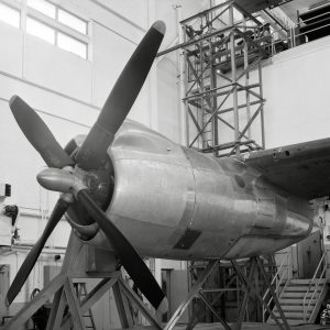
The Shop Area is an open two-story room that occupies the entire western wing of the Shop and Office Building and opens up into the high-bay in the center of the building. The AWT staff used the shop to build and disassemble engines before and after their test runs in the tunnel. The engines or other test articles were brought through the truck entrance at the front of the high-bay and set in the shop. Technicians worked with the researchers to install proper instrumentation and prepare the engine to be run in the tunnel. This often took weeks to accomplish. In 1991, the center expanded the shop and high-bay to serve as an antenna test facility.
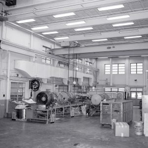
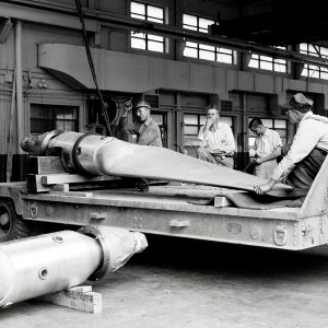
An overhead crane lifted the engine from the shop into the adjacent three-story high-bay where a 10-ton box crane carried it to the test chamber on the second floor in the rear of the building and lowered into the tunnel’s test section. Originally, there were no walls between the high-bay and the shop or the upper level of the test chamber. The high-bay was converted into the Microwave Systems Laboratory in the early 1980s. The bay served as an acoustical chamber to test large microwave antennas. In 1983, a 36-foot-high U-shaped wall was built to segregate the bay from the test section area. The facility remains in use today.
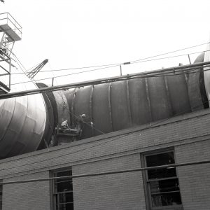
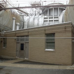
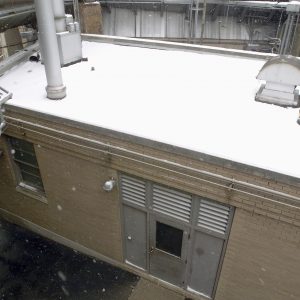
Refrigeration Building
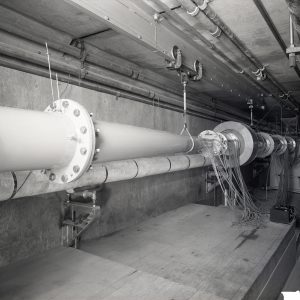
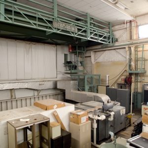
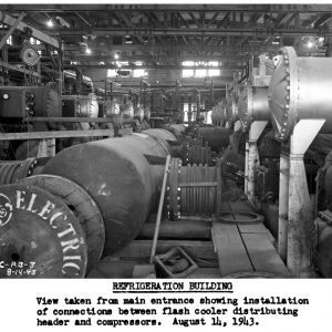
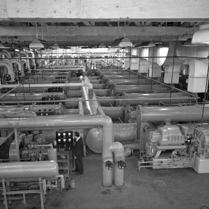
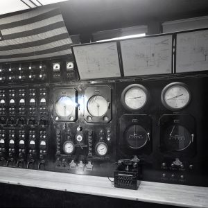
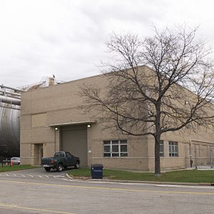
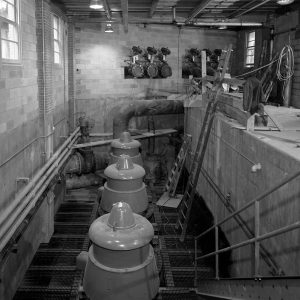
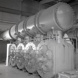
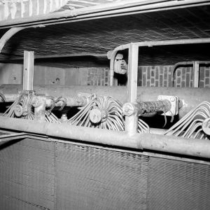
The Refrigeration Building, located just to the west of the AWT, contained the primary components of the tunnel’s cooling system. The Refrigeration Building housed 14 Carrier-designed centrifugal compressors and a flash cooler. The 1500-horsepower compressors are aligned in pairs with the cylindrical flash cooler running between them. There are also three 1,500-horsepower York compressors that were used to chill the cooling coils in the Air Dryer Building. These compressors also supply chill water for office air conditioning throughout the center. The interior of the building is largely open, but there is a small control room along the wall. There were approximately 30 different pipes connecting the flash cooler in the Refrigeration Building to the heat exchangers in the tunnel.
Documents
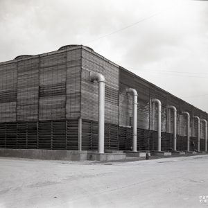
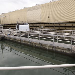
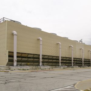
Cooling Tower No. 1 is a narrow rectangular structure behind the Refrigeration Building that expelled the heat accumulated in the circulating water. The heat-laden water circulated from the AWT was pumped to the top of the cooling tower at 63,000 gallons per minute. The water was distributed across the cooling tower and sprayed down into the 600,000-gallon basin at the bottom. Sixteen fans in the roof drew air upwards, removing energy from the heat-laden water, and expelling the heat energy to the atmosphere. The water then flowed outside into one of the three settling ponds where it cooled further before being recirculated back into the Refrigeration Building.
The cooling tower was originally a wooden structure with eight cells and settling pools off to its side. In 1951, an additional cell was added to each end of the tower. In the mid-1980s, Cooling Tower No. 1 was largely rebuilt with composite materials replacing the wood. It is still used by the Icing Research Tunnel.
As part of the 1951 AWT modernization project, a pump house was built underneath the northeast leg of the tunnel. This Circulating Water Pump House drew cooling water from the cooling tower to be used by the new exhaust system. The water was circulated through in an exhaust gas cooler tank, which reduced the temperature of the air exhausted from the tunnel. The pump house contained four Ingersoll Rand pumps, two 250-horsepower discharge pumps, two 300-horsepower spray pumps, and a 75-horsepower spray pump. The pumps were removed in the 1960s. The structure was used as a storage area until its demolition in 2008.
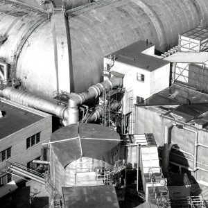
Exhauster Building
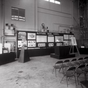
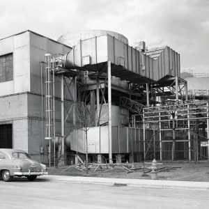
The Exhauster Building, located just east of the AWT, housed the drive motor that powered the tunnel’s fan and the exhausters and compressors that evacuated the tunnel to simulate the pressures at altitude. A smaller rectangular addition, with new, more powerful exhausters, was attached to the northeast corner of the building in 1951. In the 1960s, portions of the original building were used as part of the Solar Power Laboratory. By the mid-1970s, the large equipment had been removed, and the Exhauster Building was converted into a visitors’ center. The original structure was filled with displays, and the 1951 annex became a 170-seat assembly room. A lobby area was created at the nexus of the original building and the annex. The building was overhauled in 2010 and rededicated as the Briefing Center.
The AWT’s exhaust system was originally powered by four 1,750-horsepower Worthington exhausters located in the Exhauster Building’s large main floor area. These pumps removed the air from inside the tunnel and expelled it into the atmosphere. Following complaints from local residents during the final days of World War II, mufflers were added to the vent pipes to reduce the low-frequency vibrations which rattled nearby windows. Three Ingersoll-Rand eight-cylinder reciprocating pumps were installed in a new annex in 1951. The new exhausters significantly increased the system’s capacity. The modernization included the installation of an exhaust gas cooler, pump house, and cooler pit underneath the tunnel where the exhaust lines exited.
Documents
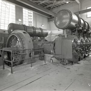
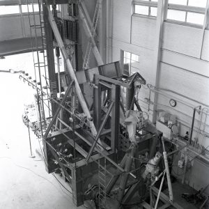
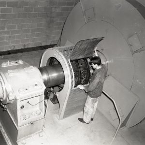
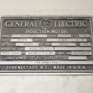
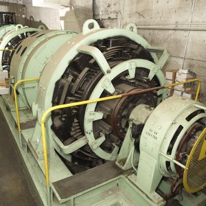
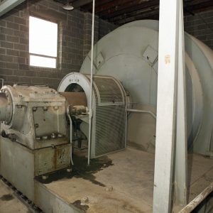
A 31-foot-long, 4,200-kilowatt generator was set up in-line with a slightly smaller unit on the first floor of the Exhauster Building. These generators created the power needed to start up the drive motor used to rotate the large fan inside the AWT. The drive system was located in a three-level tower in the southwest corner of the building. The lower level contained a small generator, and the upper two levels housed the 1800-horsepower, General Electric (GE) induction motor. The drive shaft traveled from the brick tower and into the east wall of the AWT. The AWT’s massive power loads required coordination with the local power company before operating the tunnel.
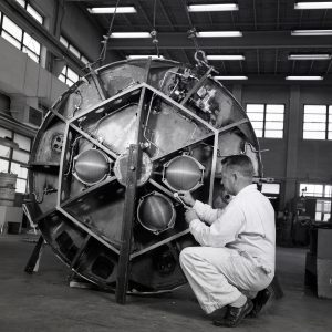
The make-up air system replenished the air that was removed from the AWT by the exhaust scoop. This make-up air was first conditioned in the Air Dryer Building. The two-story building housed the air dryer tank and two sets of cooling coils. The temperature of the atmospheric air was reduced to about 40°F as it passed through filters and cooling coils in the Primary Coils Building. The moisture in the air was reduced to a dew point of –70°F as it flowed through beds of activated alumina in the 29-foot-diameter dryer tank. The air then entered the Secondary Cooling Building north of the dryer, which cooled the air to the desired tunnel temperature. The resulting cool, dry air was pumped to both the AWT. In 1948, a new air tank was constructed on top of the existing tank and a new primary coils building built on top of the existing building.
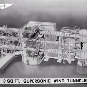
Small Supersonic Tunnels
NACA engineers took advantage of the AWT’s robust exhauster system to power several small supersonic tunnels. Three small supersonic wind tunnels, known as the Stack Tunnels because of their vertical alignment, were built in 1945, 1949, and 1951. These tunnels were housed in an L-shaped building directly behind the southwest corner of the AWT. The AWT’s make-up air system supplied the airflow for the tunnels. After passing through one of the test sections, the exhaust line tied directly into the AWT’s south wall. The control room and manometers for the facility were located in the building’s basement. The center deactivated the tunnels in 1961 during the conversion to the Space Power Chambers (SPC) and eventually demolished the building in the 1980s.
Documents
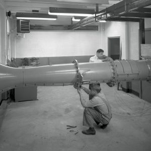
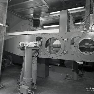
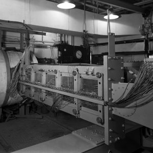
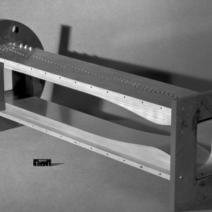
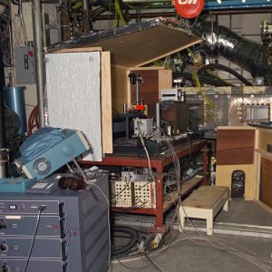
In 1945, a supersonic wind tunnel with an 8-foot-long, 4-inch-wide and 10-inch-high test section was built in a passageway in the basement of the Shop and Office Building. Like the Stack Tunnels, the Duct Lab took advantage of the AWT’s exhaust system to produce its speeds of Mach 1.6 to 5.0 and temperatures of 400°F. Operators used Schlieren and laser anemometry systems to obtain flow visualization measurements. It has been used for development of supersonic injectors, artificial intelligence methods, nonintrusive laser systems, and for flow physics studies and investigations of continuous Mach 1.6 to 5.0 flow physics. The Duct Lab continued operation into the 2000s.