Turbojet Enhancements
In the post-war years, researchers used the Jet Propulsion Static Laboratory (JPSL) to develop technologies to increase jet engine thrust.
Overview
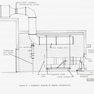
In October 1945, just weeks after the end of World War II, the Aircraft Engine Research Laboratory (AERL) reorganized its research activities to concentrate on the new technologies associated with jet propulsion and high-speed flight. The new divisions focused on different aspects of the engine: turbomachinery, fuels, materials, combustion and controls. By 1945, two additional test cells were added to the Jet Propulsion Static Laboratory (JPSL) and construction of a fifth and sixth cell would soon begin.
An alternative jet engine design emerged during the war that featured the axial-flow compressor. General Electric’s Whittle-based engines used a single centrifugal compressor. The company’s follow-up engines—the TG-180 and TG-190, as well as Westinghouse’s 19XB, 34C and others—employed an axial-flow compressor. The basic designs are explained here.
Thrust Augmentation
Although the first generation of jet aircraft were entering service, the turbojet had a long way to go before reaching its potential. One of the principal problems was the sluggish acceleration of jet aircraft. This necessitated longer runways for takeoffs and was a hazard in emergency situations and combat.
The National Advisory Committee for Aeronautics (NACA) and industry sought ways to boost thrust for short periods of time. These thrust augmentation measures included the bleedoff of exhaust gases, use of an afterburner and injection of coolants. The variable-area nozzle, which could be expanded or closed during flight, was an essential component of these strategies. The JPSL played a key role in the development of each of these methods.
Documents
- Compressors Tutorial
- Full-Scale Turbojet Engine Research Inspection Talk (1948)
- NACA Conference on Turbojet Thrust Augmentation Research (1948)
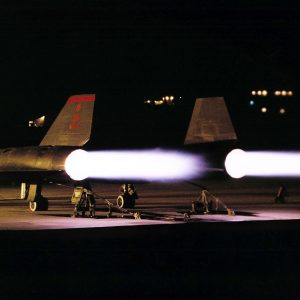
Afterburner
The most widely recognized method of boosting thrust is the afterburner, also known as tailpipe burning. Fuel is injected into the hot exhaust gas flowing between the turbine and nozzle. The combustion of the gas expands the airflow as it enters the nozzle, which increases thrust. This type of combustion requires large quantities of fuel so it can only be utilized for short boosts. The concept of combusting excess heat for additional energy is old and not unique to aircraft engines, but it was particularly applicable to the new jet engines since the increased temperatures would not damage the engine components and could be used to increase thrust.
The AERL built the first U.S. afterburner in 1944 for the General Electric I-A. Tests of the early concept on the I-A and I-16 engines in the JPSL resulted in only nominal increases in thrust due to poor combustion efficiency and pressure losses. The engineers continued to improve the design until a large afterburner was successfully operated in 1946 on a General Electric TG-180 engine in the Altitude Wind Tunnel (AWT). The performance of the initial afterburners was limited due to a lack of knowledge about the optimal design of components. AERL researchers spent the post-war years studying variations of the afterburner on different engines in the AWT and JPSL in an attempt to optimize thrust while minimizing weight and drag.
Documents – Set 1
- Afterburner Tutorial
- Summary of NACA Research on Afterburners (1956)
- Afterburner Story (1954)
- Thrust Augmentation of a Turbojet by Means of Tail-Pipe Burning (1947)
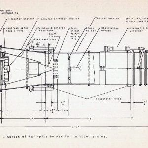
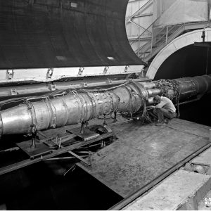
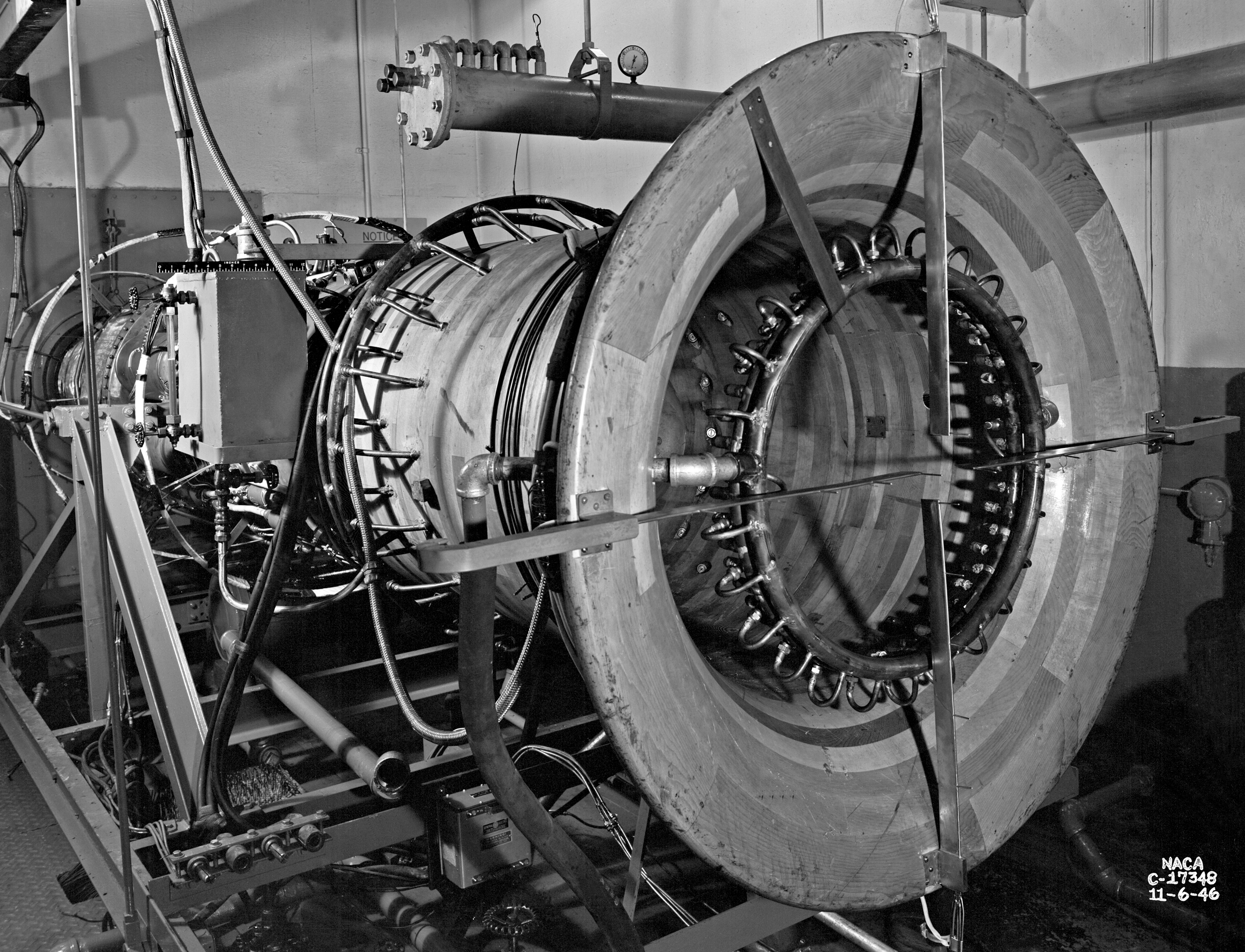
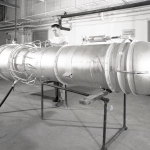
In the early 1950s, the military asked the NACA to study the use of shorter afterburners to boost thrust during takeoff for new long-range bomber and transport jet aircraft without increasing weight or pressure losses in the engine that would limit the range. The shorter afterburners required the truncating of the diffuser and combustor sections. In 1952, NACA researchers analyzed different diffuser modifications and tested the most promising on a General Electric TG-190 engine in Cell 6 of the JPSL. They continued to modify and retest the diffusers until they were able to define the minimum effective diffuser length. They then sought to shorten the combustion area to further decrease the overall size of the afterburner. A series of tests in the JPSL determined that a 36-inch chamber produced the best results.
Documents – Set 2
- Sea-Level Static Investigation of a Short Afterburner (1954)
- Performance of Short Annular Diffusers for Afterburners (1954)
- Low-Pressure-Loss Short Afterburner for Thrust Augmentation (1955)
- Afterburner with Combustion Various Chamber Lengths (1956)
Images
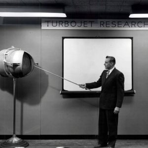
Variable-Area Nozzles
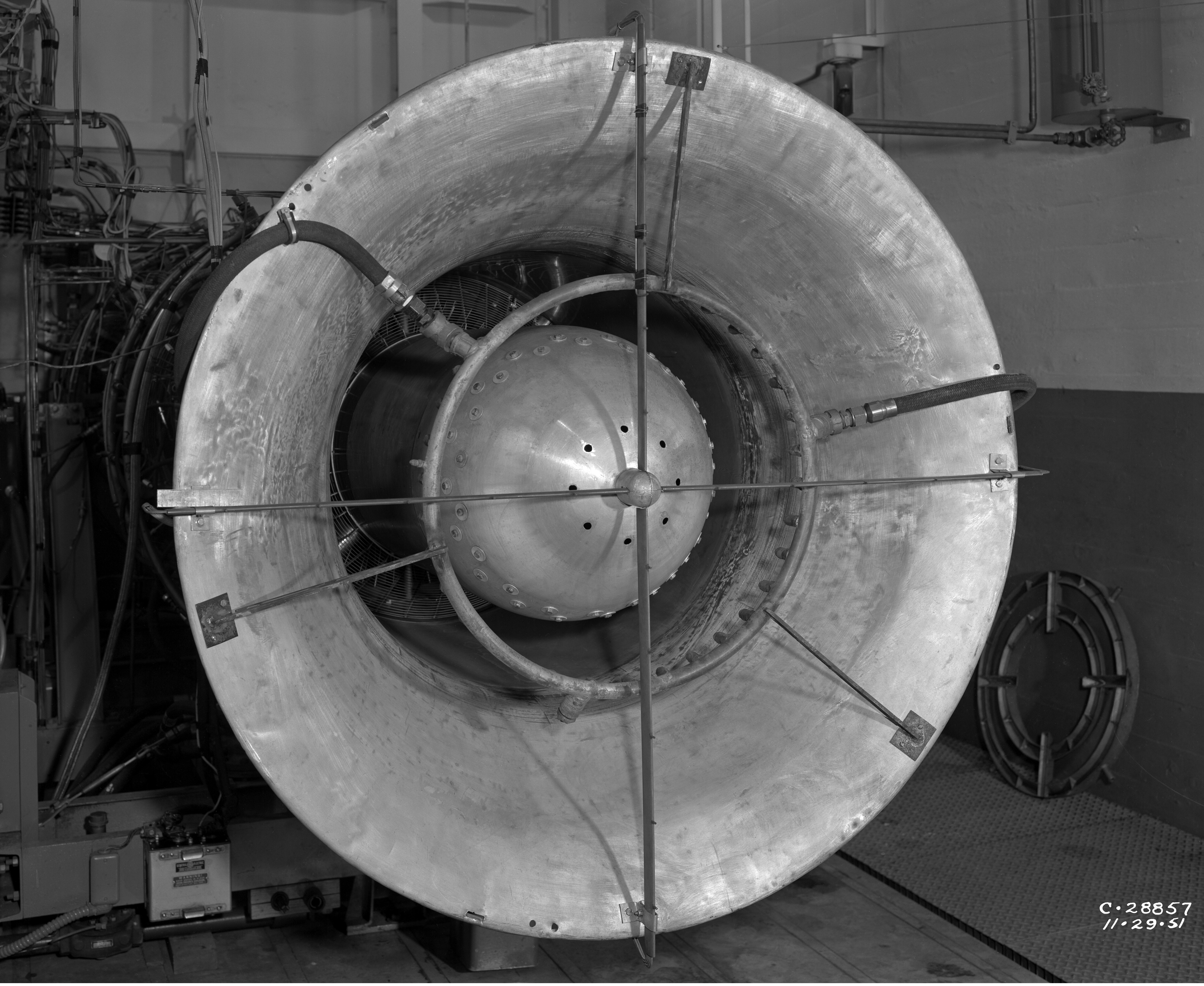
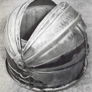
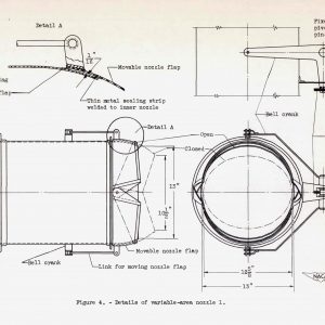
Jet engines expel their hot combustion gas into the atmosphere through a tubular nozzle, which produces thrust. Nozzles whose diameter can be adjusted during flight, known as variable-area nozzles, offered one of the best options for rapidly adjusting the thrust of a jet engine without changing engine speed. Variable-area nozzles are necessary for the use of afterburners and improve engine efficiency during normal cruising situations. Afterburner ignition produces hotter exhaust gases, which requires a larger nozzle. The variable-area nozzle is opened wide to accommodate the resultant large gas flow. This wide diameter, however, would be inefficient when the exhaust temperatures are lower during normal flight, so the variable-area nozzle is then closed.
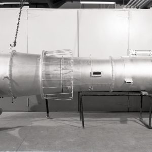
In 1943, AERL engineers designed an early clamshell-type nozzle in which two spherical flaps could be opened during afterburner operation. Researchers immediately began testing it on a General Electric I-16 engine at the JPSL. The nozzle was operated in the open and closed positions at various engine speeds. The researchers compared the data with that from similar tests of the engine in its original configuration and concluded that the adjustable nozzle performed as efficiently at a normal fixed-diameter nozzle, while providing more control.
Over the next five years, researchers tested variations of the variable-area nozzle on different turbojet models both at the JPSL and in the AWT. Although the nozzle designs were too dissimilar to compare the performance of one configuration against another, it was concluded that the overall performance was limited when the alignment of the flaps was uneven. This allowed the engine’s normal exhaust gas to leak out.
The use of variable-area nozzles was introduced into aircraft in the late 1940s and soon became standard on all jet engines. The clamshell designs were replaced by nozzles with four flaps that formed a square opening when closed. This reduced pressure losses but caused aerodynamic drag. The problem was resolved with the development of iris-shaped nozzles that retained the nozzles’ oval shape when closed.
Documents
- Tests of Adjustable-Area Exhaust Nozzle for Jet Engines (1945)
- Investigation of Several Clamshell Variable-Area Nozzles (1949)
- Thrust Control by Nozzle Area Modulation (1947)
Images:
Bleedoff Air
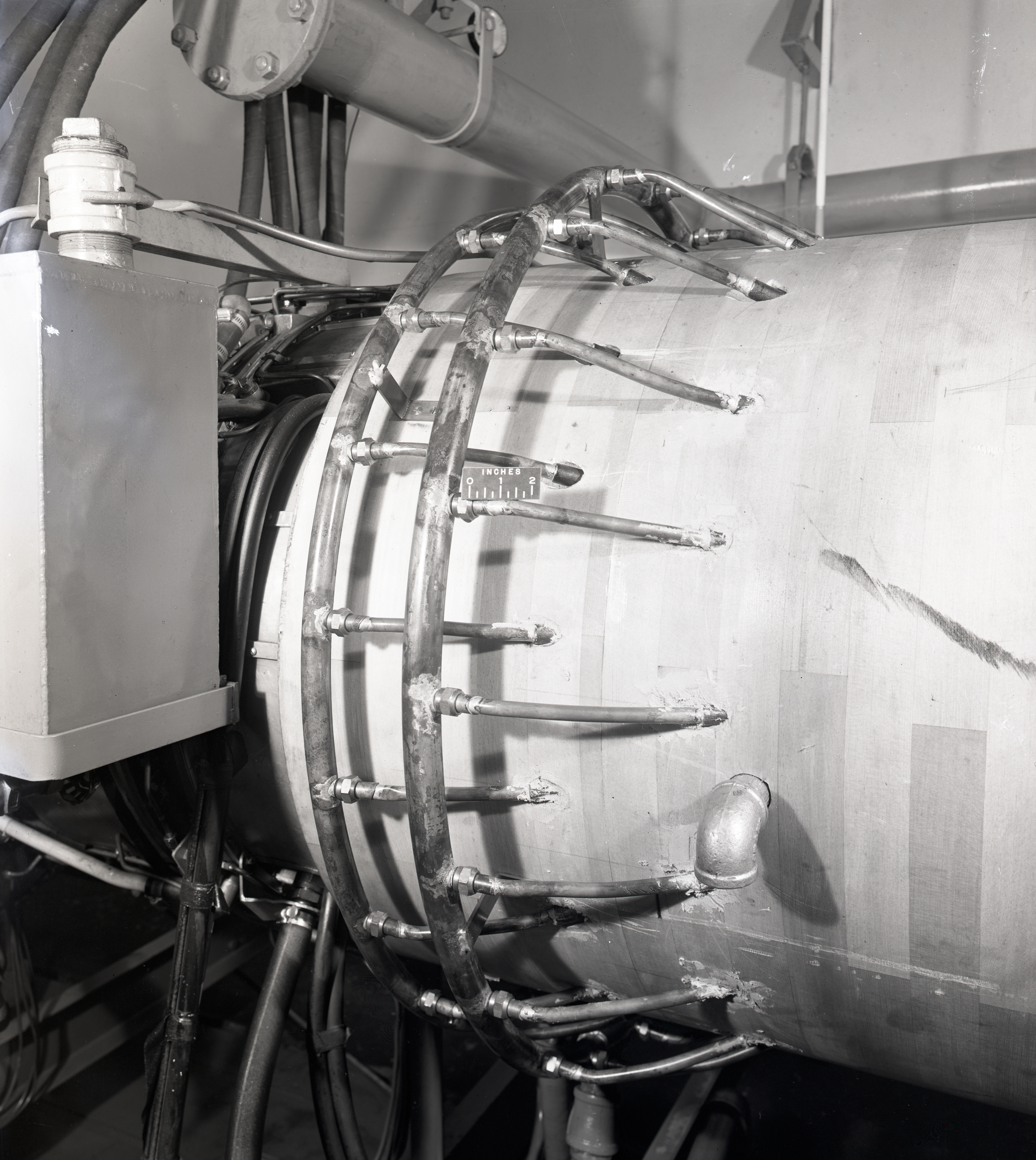
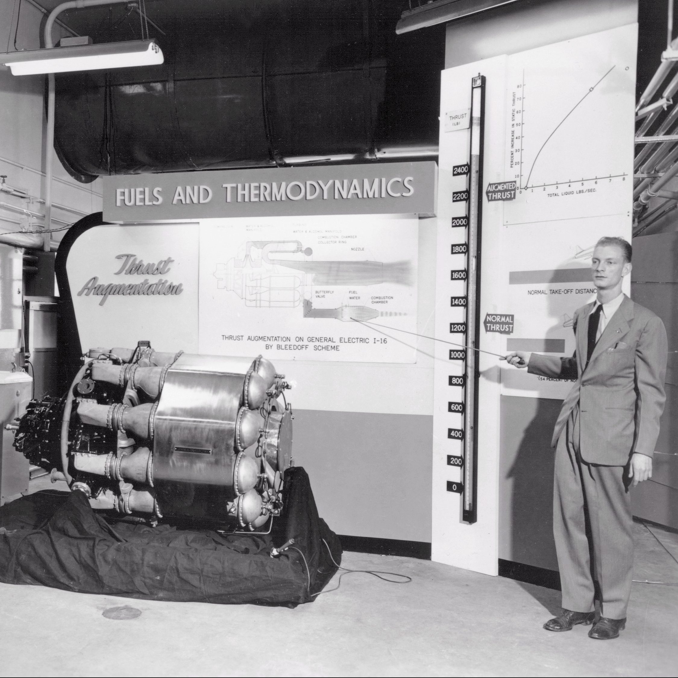
Turbines are the critical element in jet engines, which is why they are sometimes referred to as gas turbine engines. Turbine materials can only withstand so much heat, so not all of the air flow is combusted as it passes through the engine. In 1944, AERL researchers theorized that jet engine thrust could be increased by bleeding off some of this excess high-pressure air as it leaves compressor so it could be burned separately in an auxiliary nozzle. It was necessary to inject water into the inlet to replace the removed air. The water turns to steam and maintains the engine performance, while an auxiliary jet provides extra thrust.
In April 1945, AERL researchers tested the system on a General Electric I-16 in the JPSL. Although the bleedoff system required large quantities of water, it did increase thrust as predicted. They then continued the investigation using the more powerful I-40 engine to test various modifications. Although the engine’s primary thrust decreased during bleedoff, the auxiliary combustor more than made up for the loss. The researchers noted, however, that the engine had to be operated within strict parameters for the bleedoff to be successful.
Documents
- NACA Conference on Turbojet-Engine Thrust Augmentation Research (1948)
- Thrust Augmentation of 4000-Pound-Thrust Engine by Bleedoff (1950)
Images
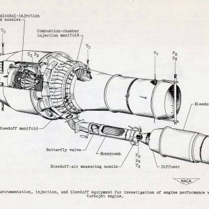
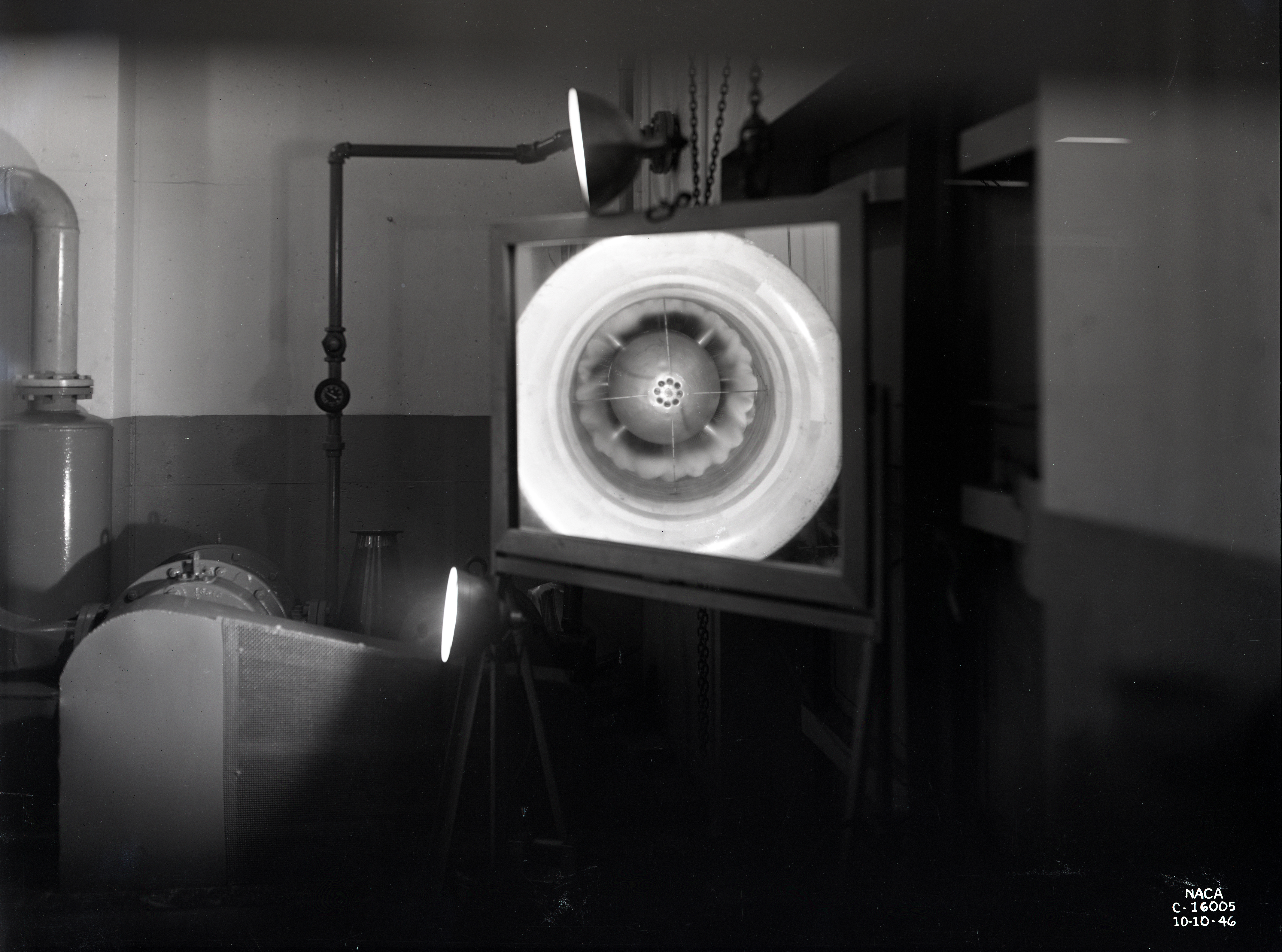
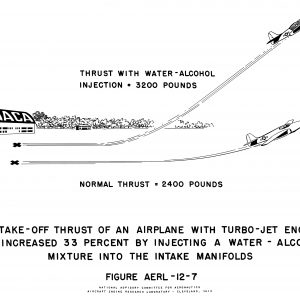
Water Injection
One of the oldest methods of thrust augmentation is the injection of a water and alcohol mixture into the inlet. Water, which is used for economical purposes, is mixed with alcohol to prevent freezing. The liquid evaporates and cools the inlet airflow before it reaches the compressor. The brief temperature reduction allows the compressor to handle larger quantities of air to be used for combustion, which results in greater thrust. The weight of the nozzles, tanks and pumps required for the system must be taken into account, however. In 1944, AERL researchers incorporated the injection system into a General Electric I-16 and tested it with water, water and alcohol, kerosene, and carbon dioxide at the JPSL. Each of the refrigerants except kerosene increased thrust by over 35 percent. The investigation continued in 1945 using the larger I-40 engine. Subsequent flight tests of the injection system on a Bell P-59A demonstrated a 21-percent increase in thrust and a reduction in the distance required for takeoff.
Documents – Set 1
- Thrust Augmentation of 1600-Pound Turbojet by Injection of Refrigerants (1947)
- Thrust Augmentation of Centrifugal-Flow Jet by Injection of Water/Alcohol (1948)

Tests of the liquid injection system on engines with axial-flow compressors, however, did not produce the same results as with the centrifugal engines. Researchers found that the greater distance between the inlet injection and the compressor limited its effectiveness. They decided to redesign the system to spray the coolant directly into the compressor stages, not the inlet. This new system was first successfully attempted on a General Electric TG-180 in Cell 6 of the JPSL. In 1950, the investigators decided to combine the liquid injection with an afterburner in a TG-180. These runs revealed that the liquid caused combustion instability and limited the performance of the afterburner. They then decided to inject the coolant into the inlet, compressor stages and combustion chamber simultaneously. Follow-up tests using a TG-190 engine tried injecting coolant into the inlet, compressor stages and combustion chamber simultaneously. The effort improved the thrust by nearly 40 percent. In addition, it was determined that unlike centrifugal engines, the axial-flow engines received the most benefit from a low injection rate.
Documents – Set 2
- Thrust Augmentation of Axial- and Centrifugal Engines by Injection (1950)
- Thrust Augmentation of Axial-Flow Turbojet by Injection at Compressor (1948)
- Thrust Augmentation of Axial-Flow Turbojet by Interstage Injection (1950)
- Thrust Augmentation by Coolant Injection and Tail-Pipe Burning (1951)
- Thrust Augmentation by Water-Alcohol Injection on Axial-Flow Turbojet (1952)
Images