Design and Analysis Software
A variety of software is used in the development of inlets and nozzles. This includes:
- Inlet-specific design and analysis tools
- Nozzle-specific design and analysis tools
- More general-purpose Reynolds-Averaged Navier-Stokes (RANS) computational fluid dynamics (CFD) simulation codes
- High-fidelity Large-Eddy Simulation (LES) flow solvers
- WIND-US
Inlet Software
SUPIN – Supersonic Inlet Design Code
SUPIN is used to design and analyze the aerodynamic performance of supersonic inlets. This includes axisymmetric pitot, three-dimensional pitot, axisymmetric outward-turning, two-dimensional single-duct, two-dimensional bifurcated-duct, and streamline-traced inlets. It combines the functionality of the older inlet codes listed below into a more up-to-date software package.
SUPIN reads a text data file containing input factors that describe the inlet geometry, design parameters, and flow conditions. It generates the geometry of the inlet and performs some design of the inlet configuration. Lastly, it calculates the aerodynamic performance in terms of the inlet flow rates, total pressure recovery, and drag.
The low-fidelity aerodynamic analysis and design methods are based on analytic, empirical, and numerical methods that provide for quick design and analysis. SUPIN generates inlet geometry in the form of coordinates, surface angles, and cross-sectional areas. It can also generate inlet surface grids and three-dimensional, structured volume grids for use with higher-fidelity computational fluid dynamics (CFD) analysis.
- Slater, J.W., “SUPIN: A Computational Tool for Supersonic Inlet Design,” GRC-E-DAA-TN28418, Jan 2016. Also AIAA-2016-0530.
- Slater, J.W., “Methodology for the Design of Streamline-Traced External-Compression Supersonic Inlets,” GRC-E-DAA-TN15478, Jul 2014. Also AIAA-2014-3593.
- Slater, J.W. and Thomas, F.C., “Design and Analysis Tools for Supersonic Inlets,” Presentation at the Fundamental Aeronautics 2009 Technical Conference: Supersonic Program, Aug 2013.
- Slater, J.W., “Design and Analysis Tool for External-Compression Supersonic Inlets,” NASA/TM-2012-217660, Aug 2012.
- Slater, J.W., “External-Compression Supersonic Inlet Design Code,” Presentation at the 2011 Fundamental Aeronautics Program Technical Conference, Mar 2011.
PINDAP – Planar Inlet Design and Analysis Process
PINDAP is a collection of software tools that allow the efficient aerodynamic design and analysis of planar (two-dimensional and axisymmetric) inlets. Inputs support parametric inlet design to efficiently model the geometry and generate the grid for CFD analysis with design changes to those parameters. The aerodynamic analysis is performed by spawning processes to the Wind-US computational fluid dynamics (CFD) program. PINDAP can be used for subsonic, supersonic, and hypersonic inlets.
- Slater, J.W., and Gruber, C.R., “Planar Inlet Design and Analysis Process (PINDAP),” NASA/TM-2005-213866, Aug 2005. Also AIAA-2005-4203.
IPAC – Inlet Performance Analysis Code
IPAC embodies a series of one-dimensional analyses that have been developed to predict the performance of a given inlet geometric design. A text input data file specifies the geometric description of a pitot, two-dimensional, or axisymmetric-spike inlet along with flow conditions.
Outputs include the inlet weight flow, total pressure recovery, and aerodynamic drag coefficient for the specified inlet geometric design. The calculated inlet performance parameters may be used in preliminary inlet design studies, subsequent engine cycle analyses, or installed engine performance calculations for existing uninstalled engine data.
- Barnhart, P.J., “IPAC-Inlet Performance Analysis Code,” NASA-CR-204130, Jul 1997.
LAPIN
LAPIN solves the quasi-one-dimensional Euler equations in a time-accurate manner to solve for unsteady flow within a supersonic mixed-compression inlet. It was intended to simulate unsteady shock motion.
- Varner, M.O., et al., “Large perturbation flow field analysis and simulation for supersonic inlets,” NASA-CR-174676, Sep 1984.
LERCINLT – Lewis Research Center Inlet Design Code
LERCINLT is a classic inlet design code that uses the method of characteristics. It can be used to design external and internal supersonic diffuser profiles of two-dimensional and axisymmetric-spike mixed-compression inlets.
The program inputs are formulated to represent the desired engineering design parameters, such as throat Mach number and flow angle. The characteristic equations are used to locate points in physical space where the flow properties change. The compatibility conditions are used to determine the flow properties.
- Anderson, B. H., “Design of supersonic inlets by a computer program incorporating the method of characteristics,” NASA-TN-D-4960, Jan 1969.
INLETMOC – Inlet Method of Characteristics
INLETMOC computes supersonic flow about and within two-dimensional and axisymmetric-spike mixed-compression inlets using the method-of-characteristics.
- Sorensen, V.L., “Computer program for calculating flow fields in supersonic inlets,” NASA-TN-D-2897, Jul 1965.
Nozzle Software
NPAC – Nozzle Performance Analysis Code
NPAC is a simple and accurate nozzle performance analysis methodology. The geometry modeling requirements are minimal and very flexible, thus allowing rapid design evaluations. The solution techniques accurately couple: continuity, momentum, energy, state, and other relations that permit fast and accurate calculations of nozzle gross thrust.
The control volume and internal flow analyses can account for the effects of over/under expansion, flow divergence, wall friction, heat transfer, and mass addition/loss across surfaces. The nozzle performance methodology results are in excellent agreement with experimental data for various nozzle designs over a range of operating conditions.
- Barnhart, P.J., “NPAC-Nozzle Performance Analysis Code,” NASA-CR-204129, Jul 1997.
Rao Nozzle Design Code
The Rao code is an optimum nozzle design code.
MOC/STT – Method of Characteristics/Streamline Tracing Tool
The MOC/SST software is a 2D and 3D Method of Characteristic (MOC) tool for designing complex nozzle geometries. These tools are GUI driven and designed for Windows-based platforms. This software was developed under contract with the Applied Physics Laboratory at John Hopkins University.
- Rice, T., “2D and 3D Method of Characteristic Tools for Complex Nozzle Development,” RTDC-TPS-481, Jun 2003.
Reynolds-Averaged Navier-Stokes (RANS) Software
FUN3D – Fully Unstructured Three Dimensions
FUN3D uses a node-based finite-volume discretization to obtain solutions on mixed-element unstructured grids. It has a variety of thermodynamics and turbulence models, as well as boundary conditions for internal flows and propulsion simulations. It supports Chimera overset grids, automatic domain decomposition, and adjoint- and feature-based grid adaptation.
- Bieden, R.T., et al., “FUN3D Manual: 13.6,” NASA/TM-2019-220416, Oct 2019.
Cart3D – Cartesian Three Dimensions
Cart3D is a high-fidelity inviscid analysis package for conceptual and preliminary aerodynamic design. It allows users to perform automated CFD analysis on complex geometry and supports steady and time-dependent simulations. Cart3D uses an embedded multilevel Cartesian mesh to discretize the space surrounding the geometry and determines the surface geometry out of the set of “cut-cells” which intersect the surface. The package features fully-integrated adjoint-driven mesh adaptation and also includes utilities for geometry import, surface modeling and intersection, mesh generation, and post-processing of results. At GRC, Cart3D has primarily been used for sonic boom calculations.
- Aftosmis, M.J., Berger, M.J., and Melton, J.E., “Robust and Efficient Cartesian Mesh Generationfor Component-Based Geometry,” AIAA Journal, Vol. 36, No. 6, 1998, pp. 952-960.15.
- Aftosmis, M.J., Berger, M.J., and Adomavicius, G., “A Parallel Multilevel Method for Adaptively Refined Cartesian Grids with Embedded Boundaries,” AIAA-2000-0808, Jan. 2000.
- Castner, R., “Cart3D Analysis of Plume and Shock Interaction Effects on Sonic Boom,” AIAA-2015-2263, Jun 2015.
Large-Eddy Simulation (LES) Software
GFR – Glenn Flux Reconstruction
GFR is a high-order computational fluid dynamics (CFD) code for large-eddy simulations. It is based on the simple and efficient flux reconstruction method.
Solution variables within each grid cell are represented by a user-selected polynomial of degree P. Solution points are added within the volume of each cell to resolve this polynomial. Similar to Discontinuous Galerkin methods, the solution may be discontinuous across cell boundaries. Arbitrary higher-order accuracy can be obtained by increasing P. GFR currently supports unstructured grids containing quadrilateral and hexahedra elements. Extension to other cell topologies is in development.
- Spiegel, S.C., DeBonis, J.R., and Huynh, H.T., “Overview of the NASA Glenn Flux Reconstruction Based High-Order Unstructured Grid Code,” GRC-E-DAA-TN28287, Jan 2016. Also AIAA-2016-1061.
- Huynh, H.T., “A Flux Reconstruction Approach to High-Order Schemes Including Discontinuous Galerkin Methods,” AIAA-2007-4079, Jun 2007.
WRLES – Wave Resolving Large-Eddy Simulation
WRLES uses high-order accurate and high-resolution numerical methods to minimize solution error and maximize the resolution of turbulent structures. Spatial discretization is performed using explicit central differencing. The central differencing schemes in the code include 2nd- to 12th-order standard central difference methods as well as 7-, 9-, 11- and 13-point dispersion relation preserving schemes. Structured multi-block grids with point-matched overlaps are required.
Solution filtering and high-order shock-capturing are included for stability. Time discretization is performed using multistage Runge-Kutta methods that are up to 4th order accurate. Several options are available to model turbulence, including Baldwin-Lomax and Spalart-Allmaras Reynolds-Averaged Navier-Stokes turbulence models, and Smagorinsky, Dynamic Smagorinsky, and Vreman sub-grid scale models for LES.
The code is used to both analyze propulsion system components and test improved LES algorithms (numerical schemes, filters, and sub-grid models).
- DeBonis, J.R., “WRLES: Wave Resolving Large-Eddy Simulation Code, Theory and Usage,” NASA/TM-2019-220192, May 2019.
FDL3DI – Flight Dynamics Laboratory Three-Dimensional Implicit
FDL3DI is a high-order accurate structured grid solver with Chimera overset grid capability. It is developed by the Air Force Research Laboratory at Wright-Patterson Air Force Base.
- Gaitonde, D.V., and Visbal, M.R., “High-order schemes for Navier–Stokes equations: algorithms and implementation into FDL3DI,” Technical Report AFRL-VA-WP-TR-1998-3060, Air Force Research Laboratory, Wright-Patterson AFB, Aug 1998.
Wind-US
Wind-US is a product of the NPARC Alliance, a partnership between the NASA Glenn Research Center (GRC) and the USAF Arnold Engineering Development Center (AEDC) dedicated to the establishment of a national, applications-oriented flow simulation capability. The Boeing Company has also been closely associated with the Alliance since its inception, and represents the interests of the NPARC User’s Association.
Wind-US solves the Euler and Navier-Stokes equations of fluid mechanics using multi-zone structured, unstructured, or hybrid grids, along with additional equation sets governing turbulent and chemically reacting flows.
Wind-US Features
Geometric Modeling
- Three-dimensional, two-dimensional, or axisymmetric configurations.
- Multi-zone structured or mixed-element unstructured grids. (Not all features of Wind-US are available for both structured and unstructured grids. See the Wind-US User’s Guide for details.)
- Abutting zones with contiguous or non-contiguous grids, or overlapping (Chimera) zones, including holes and single or double fringes.
- Stationary or rotating reference frame.
Physical Modeling
- Steady or unsteady flow.
- Compressible Navier-Stokes, thin-layer Navier-Stokes, parabolized Navier-Stokes, Euler equations.
- Perfect gas, frozen chemistry, equilibrium air, and finite-rate chemistry.
- Algebraic, one-equation, two-equation, algebraic Reynolds stress, and hybrid RANS/LES turbulence models.
- Wide variety of explicit and implicit boundary conditions for internal and external flows.
- Models for actuator disks, screens, vortex generators.
Solution Algorithms
- Block-implicit, scalar-implicit, or explicit solution operator; also Jacobi, Gauss-Seidel, MacCormack’s modified approximate factorization, ARC3D 3-factor diagonal scheme.
- First or second-order implicit time marching.
- Central differencing, and Coakley, Roe, Van Leer, Rusanov, and HLLE upwind differencing, first to fifth order.
- Explicit and implicit boundary conditions.
- Time step specified directly or through a CFL number.
- Runge-Kutta and Global Newton algorithms available.
- Convergence acceleration using grid sequencing, local CFL numbers, ramped CFL numbers.
Parallel Operation
- May be run in parallel on a multi-processor system or on a cluster of heterogeneous systems, using a fault-tolerant master-worker approach.
- Grid zones are distributed from the master to the worker systems for processing.
- PVM or MPI may be used for parallel operation. PVM software is included with Wind-US; MPI is not.
- Wind-US and PVM need not be pre-installed on worker systems.
I/O
- User input data specified using “English-like” keywords.
- Grid and solution files may be in “common file” or CGNS format.
- Wind-US common files are supported by several commercial grid generations and flow visualization programs.
Documentation & Validation
- Some of the most complete and easy to read documentation available.
- Validation archive also serves as user tutorials, complete with downloadable files.
Wind-US Documentation
Detailed information about Wind-US is available at the Wind-US Documentation web site. In addition to the documentation for Wind-US itself, documentation is also available for various pre- and post-processing programs used with Wind-US. Most of the documentation is available in both PDF and HTML form.
Wind-US Validation
There is also a detailed CFD Code Validation web site for Wind-US. The site’s objectives are: (1) to provide documented validation and example cases, with downloadable input and output files, for Wind-US; and (2) to provide analytical, computational, and experimental validation data for use by the CFD community in general.
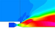
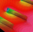
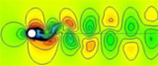
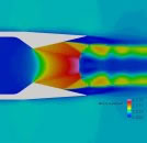
Wind-US Examples
select a thumbnail image below to open a larger image in your browser.
Use your <Back > button to return to this screen.
Image Gallery below (4 images)
Wind-US References
- Yoder, D.A., “Wind-US User’s Guide Version 4.0,” NASA/TM-2016-219145, Jul 2016.
- Nelson, C.C., “An Overview of the NPARC Alliance’s Wind-US Flow Solver,” AIAA-2010-0027, 48th AIAA Aerospace Sciences Meeting, Orlando, Florida, Jan. 4-7, 2010.
- Bush, R.H., Power, G.D., and Towne, C.E., “WIND – The Production Flow Solver of the NPARC Alliance,” AIAA-1998-935, 36th Aerospace Sciences Meeting, Reno, NV, Jan. 12-15, 1998.