Free Software Tools for Control Design, Simulation, and Analysis
One outcome of intelligent control and autonomy research is useful, cutting-edge software tools that support the development, modeling, analysis, and testing of advanced/intelligent control designs and systems health management capabilities. Many of these software tools have been made available to the public through NASA’s software and GitHub websites.
The publicly available software tools highlighted here support control system design and analysis, systems health management, propulsion system modeling, unsteady combustion modeling, and propulsion component modeling.
Control System Design & Analysis
The Tool for Turbine Engine Closed-loop Transient Analysis (TTECTrA)
Description
Systems Analysis is typically done with steady-state performance in mind. However, for complex systems such as aircraft engines, the capability to meet transient performance requirements over a wide operating envelope and a long operating life is critical. Dynamic Systems Analysis (DSA) tools and techniques have been developed which can be used to evaluate competing configurations and technologies from the perspective of being able to meet transient performance, operational life and safety requirements.
The Tool for Turbine Engine Closed-loop Transient analysis (TTECTrA) was developed as an initial step for DSA of turbofan engines. TTECTrA is an open-source software tool developed in the MATLAB/Simulink environment. The purpose of this tool is to provide the user a preliminary estimate of the transient performance of an aircraft engine without the need to design a full nonlinear controller. It is anticipated that more efficient engine designs will result by accounting for the dynamic performance capability early in the engine design stage.
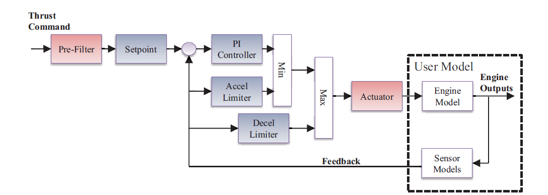
The TTECTrA generic closed-loop architecture. The Setpoint, PI controller, Accel Limiter, and Decel Limiter subsystems are designed by the TTECTrA controller, whereas the Actuator and Pre-Filter subsystems are user-defined.
References
Csank, J.T. and Zinnecker, A.M., “Tool for Turbine Engine Closed-Loop Transient Analysis (TTECTrA) Users’ Guide,” NASA/TM-2014-216663, June 2014.
Csank, J.T. and Zinnecker, A.M., “Application of the Tool for Turbine Engine Closed-loop Transient Analysis (TTECTrA) for Dynamic Systems Analysis,” AIAA 2014-3975, AIAA Propulsion and Energy Forum, Cleveland, OH, June 28-30, 2014.
Availability
The TTECTrA tool can be downloaded directly from the NASA GitHub Repository.
Systems Health Management Tools
Extended Testability Analysis (ETA) Tool
Description
The Extended Testability Analysis (ETA) Tool software was developed to extend the testability analysis capabilities of Qualtech Systems Inc.’s Testability Engineering And Maintenance System (TEAMS) Designer software. TEAMS Designer is commercial-off-the-shelf software with the capability to qualitatively model and analyze the propagation of faults through a modeled system.
The ETA Tool extracts information from the TEAMS Designer output and the associated diagnostic model to provide detailed testability analysis reports that characterize the system’s diagnostic performance. Information provided by these reports was shown to be a powerful tool for assessing compliance with system fault management requirements early in NASA’s Ares I and Artemis I design cycles.
The ETA Tool software package includes a User Guide and all files required to execute the ETA Tool software with a TEAMS example application/model. The TEAMS Designer software is not included in the ETA Tool software package.
Technical Approach
First, a fault propagation model of the system is created with TEAMS Designer – requires use of Failure Mode and Effects Analysis (FMEA) and ETA Tool naming conventions. Second, TEAMS Designer is used to generate a dependency matrix that relates failure modes to sensor-based failure detection tests. Finally, the ETA Tool can be used with model information to analyze the dependency matrix and generate testability analysis reports.
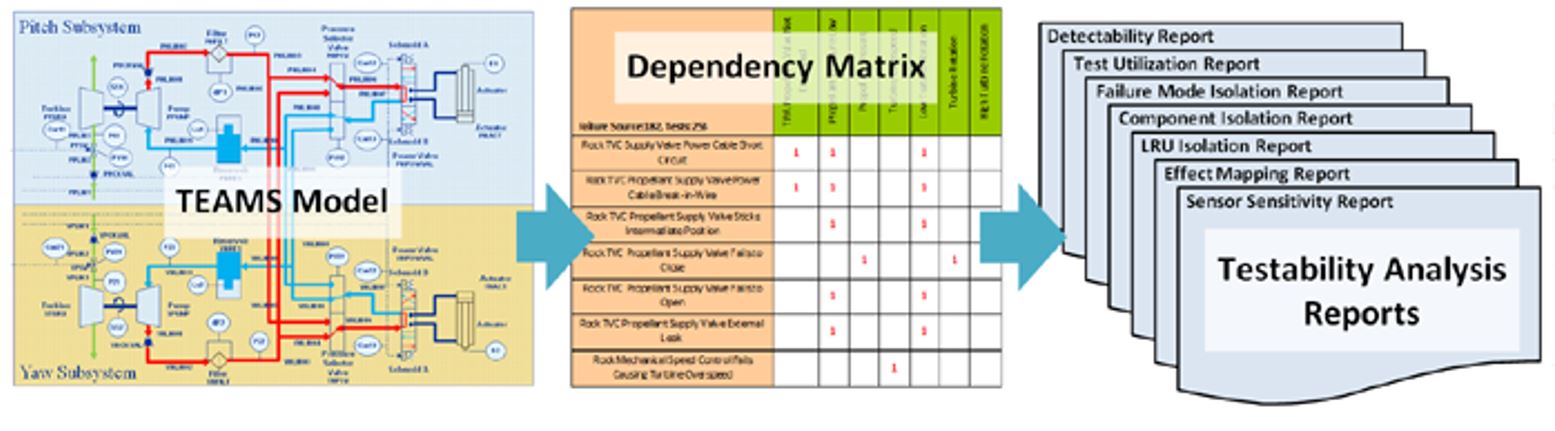
Analysis and Reporting Capabilities
- Detectability Report – Identifies failure modes that can be detected by each available failure detection test. Also identifies those failure modes that cannot be detected with any of the available failure detection tests. Allows users to identify and add tests/sensors required to detect critical failure modes early in the design process.
- Test Utilization Report – Identifies available failure detection tests that can be used to detect each failure mode. Also identifies failure mode detection tests that detect no failure modes. Allows users to identify and eliminate unnecessary tests/sensors.
- Failure Mode Isolation Report – Identifies each failure mode that can be isolated, i.e., detected solely with a unique set of failure detection tests. For failure modes that cannot be isolated, identifies ambiguity groups; where an ambiguity group is composed of multiple failure modes that are each detected with the same unique set of tests. Allows user to verify compliance with requirements to isolate individual failure modes. Additional tests/sensors could be identified early in the design process that could differentiate ambiguous failures.
- Component Isolation Report – Identifies each failure mode that can be isolated to a specific user-defined component. For failure modes that cannot be isolated to a specific component, identifies component-associated ambiguity groups. Similar to failure mode isolation, with this report the user can verify component failure isolation requirements and identify tests/sensor to differentiate ambiguities.
- Effect Mapping Report – Identifies each failure mode that can be mapped to user-defined system effects. Supports an assessment of the effect of failures on the system, e.g., vehicle-level loss of mission analysis and probability risk assessment.
- Sensor Sensitivity Report – Assesses change in diagnostic performance resulting from the removal of individual sensors or groups of sensors. The analysis can facilitate various design studies to determine the importance of specific tests/sensors, as well as diagnostic strategies to overcome sensor signal loss.
References
Maul, W.A. and Fulton, C.E., “Software Users Manual (SUM) Extended Testability Analysis (ETA) Tool, NASA/CR-2011-217240, November 2011.
Bis, R. and Maul, W., “Verification of Functional Fault Models and the Use of Resource Efficient Verification Tools,” AIAA 2015-1796, AIAA Science and Technology Forum, Kissimmee, FL, January 5-9, 2015.
Availability
The ETA Tool software is available from the NASA Glenn Software Catalog.
Propulsion Diagnostic Method Evaluation Strategy (ProDIMES)
Description
ProDiMES provides a standard benchmarking problem and evaluation metrics to enable a blind test case comparison of candidate aircraft engine gas path diagnostic methods.
Many of the propulsion gas path diagnostic method solutions published in the open literature are applied to different platforms, with different levels of complexity, addressing different problems, and using different metrics for evaluating performance. As such, it is difficult to perform a one-to-one comparison of candidate approaches. Furthermore, these inconsistencies create barriers to the effective development of new algorithms and the exchange of results. To help address these issues, the Propulsion Diagnostic Method Evaluation Strategy (ProDiMES) software tool has been specifically designed with the intent to be made publicly available. In this form it can serve as a reference, or theme problem, to aid in propulsion gas path diagnostic technology development and evaluation. The overall goal is to provide a tool that will serve as an industry standard that will facilitate the development and evaluation of significant EHM (Engine Health Management) capabilities.
ProDiMES Benchmarking Process
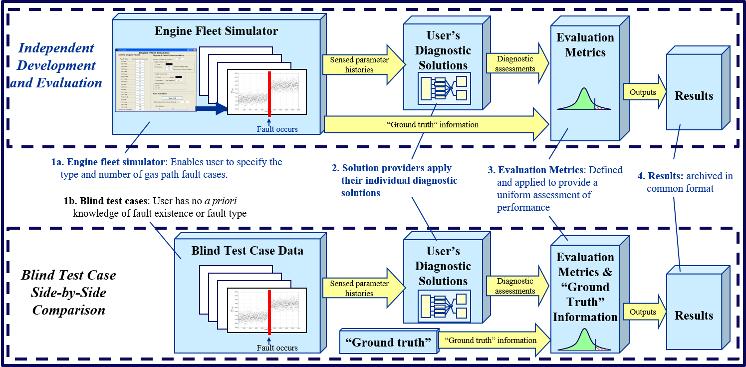
The ProDiMES tool is coded in the MATLAB environment and consists of the following functions: a) Engine Fleet Simulator (EFS) which emulates the collection of data at takeoff and cruise from a fleet of engines over their lifetime of use; b) User provided diagnostic solutions designed to process the simulated parameter histories produced by the EFS, and generate a diagnostic assessment for each engine; c) Software program which automatically evaluates and archives performance of diagnostic solutions against established metrics; and e) A set of blind test case data to enable the side-by-side comparison of diagnostic solutions developed by multiple users.
References
Simon, D.L., “Propulsion Diagnostic Method Evaluation Strategy (ProDiMES) User’s Guide,” NASA/TM-2010-215840, January 2010.
Simon, D.L., Borguet, S., Leonard, O., and Zhang, X., “Aircraft Engine Gas Path Diagnostic Methods, Public Benchmarking Results,” GTP13-1299, Journal of Engineering for Gas Turbines and Power. Apr 2014, 136(4): 041201.
Availability
ProDIMES may be requested from NASA Software.
Systematic Sensor Selection Strategy (S4)
Description
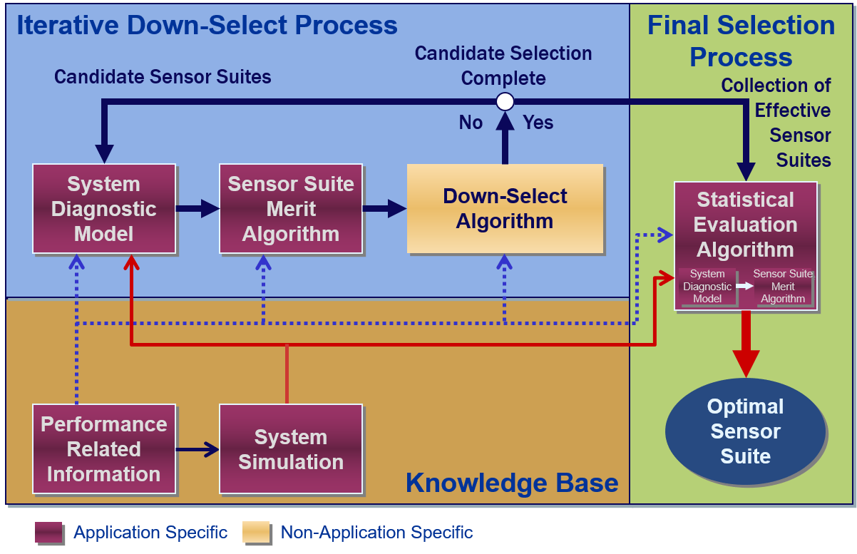
The Systematic Sensor Selection Strategy (S4) is a methodical approach for identifying a suite of sensors that optimally meets engineering requirements for a given application. S4 was developed to address the limitations of traditional aerospace sensor selection approaches that struggle to provide optimally effective sensor suite solutions for complex, interdependent system and subsystem requirements with sometimes difficult-to-identify and conflicting constraints.
In aerospace vehicle design, the proper selection of sensors is necessary to ensure that operational, maintenance performance, and more recently, system health assessment requirements are met.
Traditional approaches to measurement and sensor selection for aerospace propulsion applications are generally heuristic and are typically directed toward measuring performance characteristics rather than health diagnostics.
A typical sensor selection process begins with component teams submitting lists of desired measurements. These measurements are used to support engine development, model verification and/or detection of structural limit violations. As the system design matures, the component teams supply more detailed specifications such as measurement ranges, response requirements, and so forth.
This information along with reliability requirements is used to determine the type and number of sensors needed at each system location.
The compiled list is then separated into categories associated with measurement use, such as ground test, flight, etc. Measurements are assigned a priority, with the highest priority given to measurements required for system control.
The list is often condensed as the design matures due to factors such as accessibility, cable routing, or reduced need. A maximum number of sensors is determined based on storage and transmission capability, cost, and other considerations which may include arbitrary limits.
The component teams and chief engineer then negotiate until the final suite is selected. Consequently, sensor selection approaches such as this draw heavily on domain expertise and do not utilize a consistent quantitative method to assess the implications of measurement choices on diagnostic capability.
The Systematic Sensor Selection Strategy (diagramed above) is best described as a general architecture structured to accommodate application-specific components and requirements. Each element is intended to be customized for the target system application.
The methodology is flexible and is meant to be tailored to the specific application needs. Originally developed by NASA to support liquid propellant rocket engine health management, the S4 architecture offers the flexibility and versatility needed to support a broad range of applications, such as air-breathing engines, power systems, life support systems, ground support equipment, and general integrated vehicle health monitoring
References
Sowers, T.S., “Systematic Sensor Selection Strategy (S4) User Guide,” NASA/TM-2012-215242, February 2012.
Sowers, T.S., Kopasakis, G., and Simon, D.L., “Application of the Systematic Sensor Selection Strategy for Turbofan Engine Diagnostics,” NASA/TM-2008-215200, May 2008.
Availability
The Systematic Sensor Selection Software Package can be requested from the NASA Glenn Software Catalog.
Propulsion System Modeling Tools
Advanced Geared Turbofan 30,000(AGTF30) Model
Description
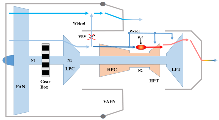
The open source AGTF30 model represents a hypothetical 30,000 lbf thrust class geared turbofan engine that includes a baseline controller, variable area fan nozzle, a gearbox connecting the low-pressure shaft to the fan shaft, and a relatively small engine core. It is representative of the types of ultra-high bypass ratio engine concepts developed under NASA sponsored N+3 studies with and engine-in-service date of 2035.
The AGTF30 model was developed using the GRC-developed Toolbox for the Modeling and Analysis of Thermodynamic Systems (T-MATS), which is based on MATLAB/Simulink. The AGTF30 is a full envelope simulation that may be run steady-state or dynamically. It has the capability to generate linear models in the form of state-space equations, which allows researchers to design, implement, and test control algorithms and concepts directly in the MATLAB/Simulink environment.
References
Chapman, J.W. and Litt, J.S., “Control Design for an Advanced Geared Turbofan Engine”, AIAA 2017-4820, 53rd AIAA/SAE/ASEE Joint Propulsion Conference, AIAA Propulsion and Energy Forum, Atlanta, GA, July 10-12, 2017.
Jones, S.M., Haller, W.J., Tong, M.T., “An N+3 Technology Level Reference Propulsion System”, NASA/TM-2017-219501, May 2017.
Availability
The AGTF30 model is available without restriction from the NASA GitHub repository
Modular Aero-Propulsion System Simulations – MAPSS, C-MAPSS, C-MAPSS40k
Description
The Modular Aero-Propulsion System Simulation (MAPSS) is a flexible turbofan engine simulation environment that provides easy access to health, control, and engine parameters through a graphical user interface (GUI). The key function of MAPSS is to provide the user with a graphical simulation environment in which to develop advanced control and diagnostic algorithms and quickly test them on a generic turbofan engine simulation. MAPSS can be used to generate state-space linear models, from which the user may create a piecewise linear controller. MAPSS can also run transient simulations. This capability allows the user to test the performance of their algorithms on a validated, and verified, generic engine model.
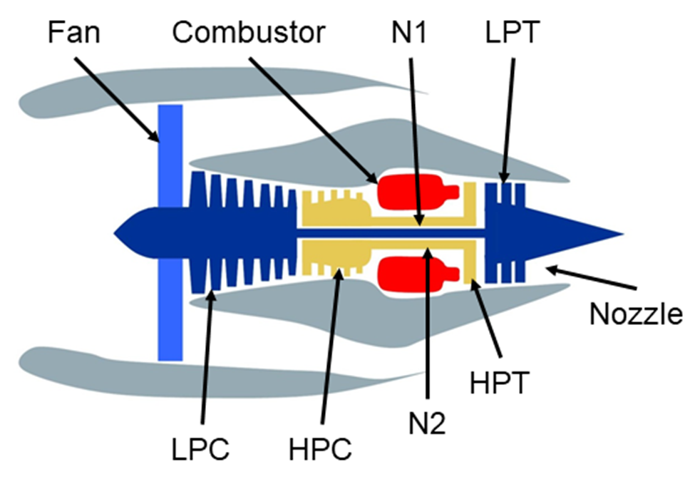
Both military and commercial turbofan engine versions of MAPSS exist. The military version, referred to simply as MAPSS, is representative of a low-bypass, high-pressure ratio engine with an advanced multivariable controller. The commercial versions, C-MAPSS and C-MAPSS40k, represent high-bypass engines capable of 90,000 lbf thrust and 40,000 lbf thrust, respectively. They also feature realistic full-authority digital engine controllers (FADEC) and run faster than real-time.
References
May, R.D., Csank, J., Lavelle, T.M., Litt, J.S., and Guo, T., “A High-Fidelity Simulation of a Generic Commercial Aircraft Engine and Controller,” NASA/TM-2010-216810, AIAA-2010-6630, October 2010.
Liu, Y., Frederick, D.K., DeCastro, J.A., Litt, J.S., and Chan, W.W., “User’s Guide for the Commercial Modular Aero-Propulsion System Simulation (C MAPSS) Version 2,” NASA/TM—2012-217432, March 2012.
Frederic, D.K., DeCastro, J.A., Litt, J.S., “User’s Guide for the Commercial Modular Aero-Propulsion System Simulation (C-MAPSS),” NASA/TM-2007-215026, October 2007.
Availability
MAPSS is a U.S. Release, meaning that it is available to U.S. persons only. C-MAPSS (original and version 2) and C-MAPSS40K are currently available as U.S. Government Purpose Releases. This means that software release will be granted on a case-by-case basis to a U.S. organization for use on a relevant contract directly with an agency of the U.S. Government. These models may be requested from NASA Software.
T-MATS: Toolbox for the Modeling and Analysis of Thermodynamic Systems
Description
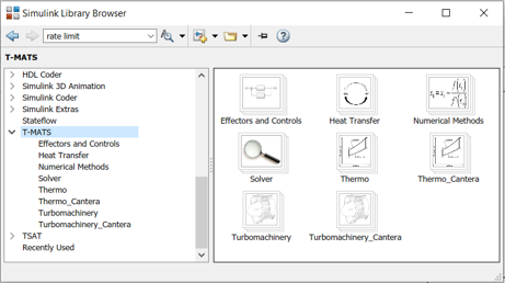
T-MATS is a graphical thermodynamic simulation toolbox built in the MATLAB/Simulink software package. It combines generic thermodynamic and controls modeling capability with a numerical iterative solver to create a framework for the creation of complex simulations. T-MATS utilizes numerical methods including a Newton-Raphson iterative solver and Jacobian calculations. A feature of the package is the turbomachinery block set. This set of Simulink blocks gives developers the tools required to create virtually any steady-state or dynamic turbomachinery simulation, e.g., a gas turbine engine simulation. In systems where the control system or other related components are modeled in MATLAB/Simulink, the T-MATS developer can create the complete system in a single tool.

References
Chapman, J.W., Lavelle, T.M., May, R.D, Litt, J.S., Guo, T., “Toolbox for the Modeling and Analysis of Thermodynamic Systems (T-MATS) User’s Guide,” NASA/TM-214-216638, January 2014.
Chapman, J.W., Lavelle, T.M., May, R.D., Litt, J.S., Guo, T-H., “Propulsion System Simulation Using the Toolbox for the Modeling and Analysis of Thermodynamic Systems (T-MATS),” AIAA 2014-3929, NASA/TM-2014-218410, AIAA Joint Propulsion Conference, Cleveland, OH, Jul 28-30, 2014.
Lavelle, T.M., Chapman, J.W., May, R.D., Litt, J.S., and Guo, T.H., “Cantera Integration with the Toolbox for the Modeling and Analysis of Thermodynamic Systems (T-MATS),” AIAA 2014-3932, AIAA Joint Propulsion Conference, Cleveland, OH, Jul 28-30, 2014.
Chapman, J.W., Lavelle, T.M., Litt, J.S., Guo, T-H., “A Process for the Creation of T-MATS Propulsion System Models from NPSS Data,” AIAA 2014-3931, NASA/TM-2014-218409, AIAA Joint Propulsion Conference, Cleveland, OH, Jul 28-30, 2014.
Availability
T-MATS is available without restriction from the NASA GitHub Repository
Unsteady Combustion Modeling Tools
Simplified Pulse Detonation Engine Performance Code
Description
The code is a simplified (lumped volume), spreadsheet-based, time-dependent, pulse detonation engine simulation which predicts semi-idealized, design-point performance of a defined configuration in terms of flow rate, specific thrust, and specific impulse.
References
Paxson, D.E., Brophy, C.M. and Bruening, G.B.,
“Performance Evaluation of a Pulse Detonation Combustion Based Propulsion System Using Multiple Methods, ”
JANNAF Journal of Propulsion and Energetics, Vol. 3, No. 1, May, 2010, pp 44-54,
Proc. JANNAF 42nd Combustion Subcommittee, 30th Airbreathing Propulsion Subcommittee, 30th Exhaust Plume Technology Subcommittee, 24th Propulsion Systems Hazards Subcommittee, 12th SPIRITS User Group Joint Meeting, Newton, MA, JSC CD-53 (CD ROM) CPIAC Abstract No. 2008-0006BW, May 2008.
Availability
The ” Simplified Pulse Detonation Engine Performance Code ” maybe be obtained by contacting the NASA Glenn Technology Transfer and Partnership Office.
Quasi-One-Dimensional Reactive Code for Design and Analysis of Gasdynamic-Based Propulsions Systems
Description
The Quasi-One-Dimensional Reactive Code for Design and Analysis of Gasdynamic-Based Propulsion Systems is a time-accurate, quasi-one dimensional, single-species, reactive CFD code for design and analysis of gasdynamic-based propulsion systems. These include, but are not limited to, wave rotor-based pressure exchange devices, internal combustion wave rotors, detonative or deflagrative mode constant volume combustors, Pulse Detonation Engines, and combinations thereof. The code uses established numerical techniques for integrating the equations of motion, but also contains original sub-models to account for dominant and unavoidable loss mechanism.
It possesses robust boundary condition sub-routines that allows for different modes of flow (inflow, outflow, sub or supersonic) in any of the envisioned ducts to which a gasdynamic device must be coupled. Thus, the correct flowfield is evolved rather than being imposed (which often leads to failures when numerically integrating). Additionally, the structure of the code is versatile, allowing for devices with stationary or rotating tubes or channels of arbitrary cross section. Because the code is quasi-one dimensional, it runs relatively quickly. This in turn allows for parametric analysis and design of conceptual devices and existing experimental rigs. However, because it is CFD based, with validated sub-models, the code output is realistic and vastly superior to simple thermodynamic analysis techniques often employed on gasdynamic devices.
Gasdynamic based propulsion systems are inherently unsteady, or time dependent. The mathematical equations that govern their operation cannot be integrated or solved in closed form. Attempts to analyze such systems with traditional steady-state analysis typically results in performance predictions that are overly optimistic.
Furthermore, steady state analysis conveys no useful design information. That is to say, a device that relies on precise timing of valves, sparks, wave transit times, etc., is impossible to build when time is neglected. Furthermore, it has been shown historically that even when an unsteady analysis is conducted (for example the method of characteristics, or thin wave techniques), if the dominant loss mechanisms are not considered, experimental articles built using this analysis will perform well below predictions.
Thus, there is a need for a relatively fast, yet reasonably accurate simulation capability that is generic enough to accommodate disparate gasdynamic concepts. This code fulfills that need.
References
Nalim, R. M., and Paxson, D. E., “A Numerical Investigation of Premixed Combustion in Wave Rotors,” ASME Journal of Engineering for Gas Turbines and Power, Vol. 119, No. 3, 1997, pp. 668-675, also ASME Paper 96-GT-116, June, 1996, also, NASA TM 107242.
Paxson, D. E., “Performance Evaluation Method for Ideal Airbreathing Pulse Detonation Engines,” AIAA Journal of Propulsion and Power, Vol. 20, No. 5, 2004, pp. 945-947.
Paxson, D.E., Wilson, J., Welch, G.E., “Comparison Between Simulated and Experimentally Measured Performance of a Four Port Wave Rotor,” AIAA 2007-5049, July, 2007.
Paxson, D.E., Naples, A.G., Hoke, J.L., Schauer, F. “Numerical Analysis of a Pulse Detonation Cross Flow Heat Load Experiment,” AIAA-2011-584, January, 2011.
Availability
The “Quasi-One Dimensional Reactive Code for Design and Analysis of Gasdynamic-Based Propulsion Systems” maybe be obtained by contacting the NASA Glenn Technology Transfer and Partnership Office.
Sectored-one-dimensional Combustor Code
Description
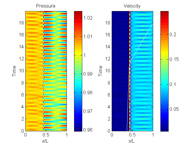
The Sectored-One-Dimensional (S1D) Combustor Code is a time-Accurate, sectored-one-dimensional, single-species, reactive CFD code for simulation, analysis and control of gas-turbine combustion systems. In particular, the code is developed to investigate those combustor configurations which are susceptible to, or exhibit, so-called thermo-acoustic instabilities. The code uses established numerical techniques for integrating the equations of motion but contains a unique routine whereby one-dimensional regions of differing cross sections are coupled at their common boundary.
Thus, the code accommodates the abrupt area changes characteristic of modern low-emission combustors while maintaining a simple one-dimensional structure throughout the remainder of the combustor. Because it is a physics-based code or simulation, unstable behavior (if it occurs) is manifested as the code integrates in time. That is to say, the instable behavior is not brought about by any sort of external forcing, or internal sub-model. It arises quite naturally and correctly due to interactions between heat release and acoustic pressure waves.
Lean-premix, low emission combustor designs appear to be particularly susceptible to the phenomenon of thermo-acoustic instability. This is due, among other things, to their lack of cooling air and their acoustically stiff geometry. One possible solution to the instability problem is active or feedback control. Here, a signal from the system (e.g., pressure) is used to detect incipient instabilities, and some form of actuation (such as fuel flow perturbation) is used to suppress and re-stabilize the system. A successful active control design is, however, greatly enhanced by accurate modeling and simulation of the combustor of interest, and by straightforward implementation of simulated actuation and control strategies. The essential physical phenomena should be correctly captured.
On the other hand, dynamic characterization of the system required for control design necessitates parametric analyses and multiple simulation runs. This, in turn, places the practical requirement of high speed on the simulation.
If the instabilities are predominantly oriented along one spatial dimension, and if consideration is limited to premix type combustion, then it may be possible to satisfy the simulation objectives of numerical speed (i.e. model simplicity), and physical accuracy. Such restrictions apply to a large number of combustor designs. The NASA S1D code achieves the goals just described with the added, essential, capability of accounting for the large and abrupt changes in cross sectional area typically associated with premix combustors.
References
Paxson, D.E., “A Sectored-One-Dimensional Model for Simulating Combustion Instabilities in Premix Combustors,” NASA/TM-1999-209771, AIAA-2000-0313, 38th AIAA Aerospace Sciences Meting & Exhibit, Reno, NV, January 10-13, 2000.
Paxson, D.E. and Metha, V.R., “Using the NASA GRC Sectored-One-Dimensional Combustor Simulation,” NASA/TM-2014-2166623, March 2014.
Availability
The Sectored-One-Dimensional Combustor Code may be requested from NASA Software. This is non-commercial, research code written in FORTRAN. Source files and brief user-manuals are available.
Propulsion Component and Other Modeling Tools
Compressible Flow Toolbox
Description
The Compressible Flow Toolbox is a collection of algorithms that solve almost 300 linear and nonlinear classical compressible fluid flow relations. The novel approach solves the following linear and nonlinear equations to obtain relationships between relevant flow parameters.
- Isentropic Flow Equations
- Fanno Flow Equations (flow with friction)
- Rayleigh Flow Equations (flow with heat transfer)
- Normal Shock Equations
- Oblique Shock Equations
- Prandtl-Meyer Expansion Equations
The toolbox is implemented in the MATLAB programming language and is useful for analysis of 1-D steady flow with constant entropy, with friction, with heat transfer, or with supersonic Mach numbers. The toolbox also contains algorithms to compare and validate the software against existing solutions.
References
Melcher, K.J., “User Guide for Compressible Flow Toolbox Version 2.1 for Use With MATLAB(Registered Trademark); Version 7,” NASA/TM-2006-214086, January 2006.
Availability
The Compressible Flow Toolbox may be requested at software.nasa.gov.
EADIN: Engine Area Distributed Interconnect Network Communications Model
Description
Engine Area Distributed Interconnect Network (EADIN) is a network communication protocol and bus created to support distributed engine control research. This network is a candidate for distributed control systems on aircraft engines and was developed by the Distributed Engine Control Working Group (DECWG) http://www.decwg.org. EADIN features a master node that organizes communication between up to 16 other nodes in a hard-real-time fashion. Our specific implementation of the protocol, which is called EADIN Lite, was used to demonstrate that an aircraft engine simulation with distributed sensors/actuators could be successfully controlled and to study the how minimum network speed is affected by cybersecurity requirements.
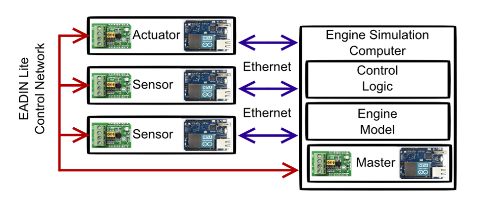
The EADIN Lite communication protocol uses a series of nodes implemented on microcontrollers communicating over an RS-485 network. A master node distributes information between nodes through a call and response system. Support nodes sense and record pressures and temperatures and simulate actuators. The protocol is hard-real-time, meaning that messages from nodes have a limited window to respond to information requests and information that arrives late is ignored. The RS-485 network is simplex and thus does not allow multiple nodes to talk at the same time. No time synchronization between nodes is required for this network.
These factors enable the master to request information from sensors and command actuators, one at a time. All information must pass from individual nodes to the master node before being sent to the engine control system.
While other communication protocols like ModbusMaster and Simple-Modbus exist, the speed of these communication protocols on the RS-485 network was not sufficient for distributed engine control which required message send to reply receipt times of 1 millisecond. Additionally, the other protocols were not hard-real-time or did not implement the same message system as specified by the preliminary documents regarding the EADIN protocol.
References
Aretskin-Hariton, E.A., Thomas, G. Kratz, J.L., and Culley, D.E., “Design and Benchmarking of a Network-In-the-Loop Simulation for Use in a Hardware-In-the-Loop System,” AIAA 2017-1943, AIAA Science and Technology Forum, Grapevine, TX, January 9-13, 2017.
“EADIN Lite Communication Network”, Tech Briefs: Engineering Solutions for Design & Manufacturing, NASA John H. Glenn Research Center, Cleveland Ohio, December 1, 2015
Berner, Andrew., “Engine Area Distributed Interconnect Network – EADIN a DECWG Proposed Serial Communication Bus for SAE Consideration”, #12AEAS-0136 , SAE Aerospace Electronics and Avionics Systems Conference, Phoenix, AZ, October 30-November 1, 2012.
Availability
EADIN is available from the NASA GitHub Repository.
EMTAT: Electrical Modeling And Thermal Analysis Toolbox
Description
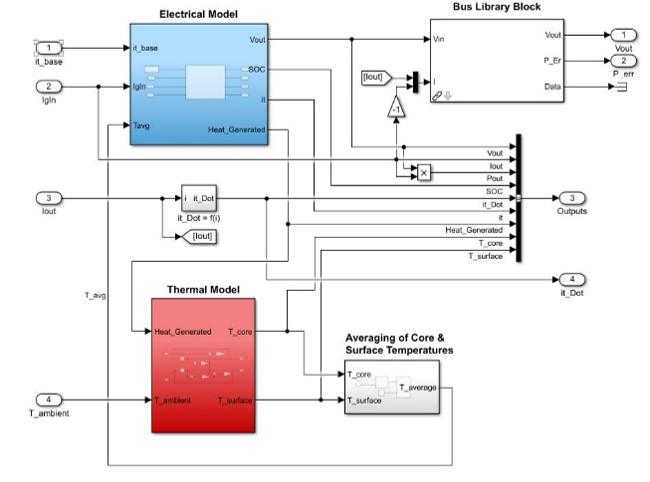
The Electrical Modeling and Thermal Analysis Toolbox (EMTAT) is a MATLAB/Simulink-based building block graphical tool used to create simulations of electrical/power systems. EMTAT is specifically designed to simulate electric/electrified propulsion systems at the level of fidelity (time scale) appropriate to capture interactions with turbomachinery.
EMTAT contains blocks that represent electrical components (batteries, motors/generators, inverters, etc.) modeled using either power flow or physics-based representations. EMTAT is compatible with the Toolbox for the Modeling and Analysis of Thermodynamic Systems (T-MATS) for simulations that require mechanical components (turbomachinery, shafts, propellers, etc.). For such mixed simulations (i.e., those containing both electrical components and turbomachinery), the EMTAT blocks can use the T-MATS solver, allowing the relevant electrical and mechanical variables to be solved simultaneously.

References
Bell, M.E., Litt, J.S., “Electrical Modeling and Thermal Analysis Toolbox (EMTAT) User’s Guide,” NASA/TM-20205008125, October 2020.
Bell, M.E., Litt, J.S., “An Electrical Modeling and Thermal Analysis Toolbox for Electrified Aircraft Propulsion Simulation,” AIAA 2020-3676, AIAA Propulsion and Energy Forum, virtual event, August 24-28, 2020.
Availability
EMTAT may be requested at software.nasa.gov.
TCML: Tip Clearance Modeling Library
Description
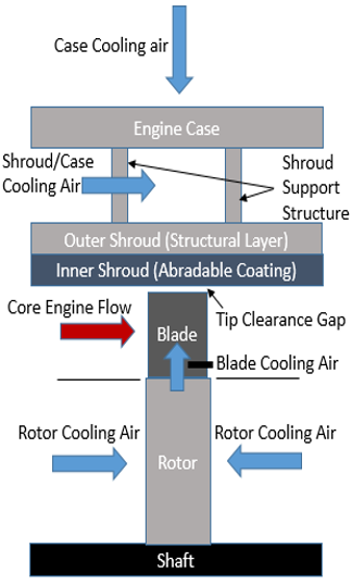
provides a set of parameterized Simulink blocks that implements a system-level physics-based modeling approach to approximate the steady-state and dynamic variation of the tip clearance gap within turbomachinery. The tip clearance gap is of interest because it can have a significant impact on turbine and overall engine performance. The tip clearance varies throughout a flight as mechanical and thermal loads change. The toolset was developed in an effort to model transient changes in tip clearance for the high-pressure turbine in a compact gas turbine engine. The goal was to characterize the tip clearance variation to capture performance impacts and to allow for the design and evaluation of faster tip clearance control approaches. The parameterized Simulink blockset can be integrated with an engine model such as one developed using the Toolbox for Modeling and Analysis of Thermodynamic Systems (T-MATS).
References
Chapman, J., Kratz, J., Guo, T.H., and Litt, J., “Integrated Turbine Tip Clearance and Gas Turbine Engine Simulation,” AIAA 2016-5047, Proceedings of the 52nd AIAA/ASME/SAE/ASEE Joint Propulsion Conference, Salt Lake City, UT, July 25-27, 2016.
Kratz, J., Chapman, J., and Guo, T.H., “A Parametric Study of Actuator Requirements for Active Turbine Tip Clearance Control of a Modern High Bypass Turbofan Engine,” GT2017-63472, Proceedings of the 2017 ASME Turbo Expo, Charlotte, NC, 2017.
Kratz, J., and Chapman, J., “Active Turbine Tip Clearance Control Trade Space Analysis of an Advanced Geared Turbofan Engine,” AIAA 2018-4822, Proceedings of the 54th AIAA/ASME/SAE/ASEE Joint Propulsion Conference, Cincinnati, OH, July 9-11, 2018.
Availability
TCML available from the NASA GitHub repository.
TSAT: Thermal Systems Analysis Toolbox
Description
This Open Source software is a graphical thermal system modeling and simulation package built in MATLAB/Simulink (The Mathworks, Inc). These tools were created through an effort to develop thermal models for gas turbine engines with an eye toward control component reliability as it relates to distributed engine control. However, its applications are more generic than this. TSAT provides tools of a varying level of fidelity including 1-D and 2-D heat conduction blocks that implement finite difference methods, and more simplistic approaches such as lumped capacitance heat transfer modeling.
The toolbox touches on a number of topics including conduction, convection, radiation, thermal deformation, fluid heat transfer, approximation of thermal properties for air, and includes various general-use tools. A variety of the tools can be used to facilitate the generation of boundary conditions while some others perform specific thermal modeling functions. The comprehensive set of tools provide the building blocks to construct dynamic models that can be used to predict heat transfer and the thermal state of various physical systems.

References
Kratz, J., Culley, D., Chapman, J., “Approximation of Engine Casing Temperature Constraints of Casing Mounted Electronics,” AIAA 2016-4858, Proceedings of the 52nd AIAA/ASME/SAE/ASEE Joint Propulsion Conference, Salt Lake City, UT, July 25-27, 2016.
Kratz, J., and Chapman, J., “Active Turbine Tip Clearance Control Trade Space Analysis of an Advanced Geared Turbofan Engine,” AIAA 2018-4822, Proceedings of the 54th AIAA/ASME/SAE/ASEE Joint Propulsion Conference, Cincinnati, OH, July 9-11, 2018.
Kratz, J., Culley, D., and Thomas, G., “Thermal Modeling of an Advanced Geared Turbofan for Distributed Engine Control Application,” AIAA 2018-4659, Proceedings of the 54nd AIAA/ASME/SAE/ASEE Joint Propulsion Conference, Cincinnati, OH, July 9-11, 2018.
Availability
TSAT is available from the NASA GitHub repository.