Implementation
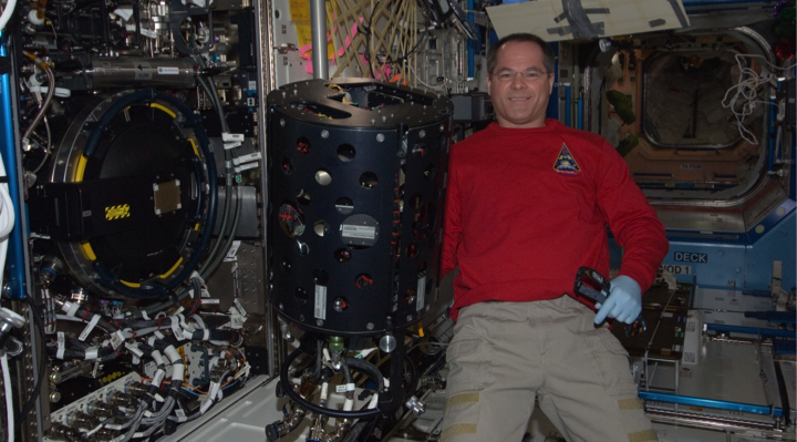
The ACME experiments will be conducted with a single modular set of hardware in the Combustion Integrated Rack (CIR) on the International Space Station (ISS), where the CIR is depicted below.
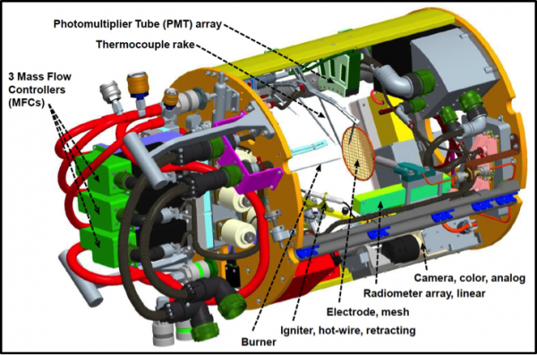
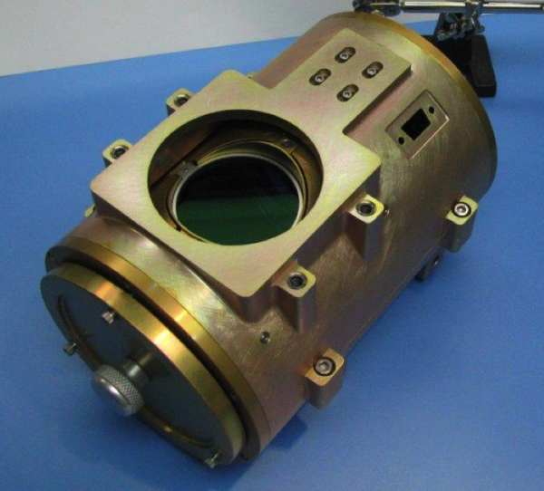
The three main elements of the ACME-unique hardware are the chamber insert (shown below), a high-definition color camera, and an avionics package (for data acquisition and control and also depicted below).
 |
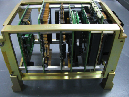 |
| Engineering model of the ACME avionics package, with the internal card stack shown at the right (where the two photographs are at different scales). | |
Burners and Igniter
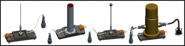
- ACME provides common mounting (on the chamber axis) of a variety of burners, which are depicted and described below.
- Most burners will be equipped with a surface thermocouple, and each burner for the BRE experiment will have two heat flux transducers.
- The internal pressure of the porous burners will be measured to allow monitoring of the pressure differential across the outlet surface.
- The retracting and resistively heated igniter will have a crew-exchangeable tip and arm (to accommodate the various burners) and its stepper-motor drive will allow for precise positioning.
Gas Delivery
- ACME’s chamber insert includes three mass flow controllers for the delivery of fuel, oxidizer or inert (e.g., helium or carbon dioxide), and nitrogen to the burner or for chamber filling.
- The maximum fuel flow is 2 slpm (on a nitrogen basis), whereas much higher flows, e.g., 10 slpm (on a nitrogen basis), are possible for the oxidizer and nitrogen lines. The crew can exchange the mass flow controllers to provide appropriate ranges that maximize the flow accuracy.
- The gas delivery system enables on-orbit dilution of the fuel or oxidizer (but not both simultaneously), coflow flames, inverse flames (e.g., oxidizer delivery to the center of a coflow burner), and premixed flames, although the latter are not planned for any of the current ACME experiments.
- Gases can also be delivered premixed to the space station where that is necessary in some circumstances, such as the blending of different fuel gases.
- CIR’s standard bottle sizes are 1, 2.25, and 3.8 liters but ACME will sometimes use smaller bottles as a hazard control to limit the deficient reactant (e.g., fuel) that can be released into the combustion chamber.
Imaging Overview
- ACME’s primary flame diagnostics are a suite of imaging systems including five video cameras and two illumination systems. Three of the cameras and one illumination system are part of the CIR facility and are already in use on orbit.
- Collectively, the imaging systems will enable color, CH*, and OH* imaging; pyrometry; measurement of the soot volume fraction; and/or operational support.
- All but one of the cameras is mounted outside of the chamber.
Color Imaging
- Color imaging is provided by two video cameras: a high-definition digital camera mounted outside of the chamber and a standard analog camera mounted on the chamber insert (with a turning mirror).
- Both cameras are part of the ACME hardware that is now in development.
- The signal from the analog camera (shown below) will be downlinked in near real time to support the experiment operations, where Light-Emitting Diodes (LEDs) within the chamber can be used to illuminate the igniter and burner to both support the operations and provide reference images.
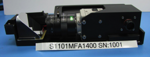
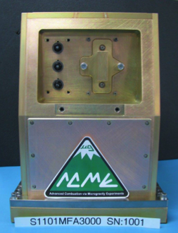
- The 12-bit digital camera (shown below) records at up to 30 full frames (1360×1024) per second, and is equipped with a motorized lens with independent control of the zoom, iris, and focus.
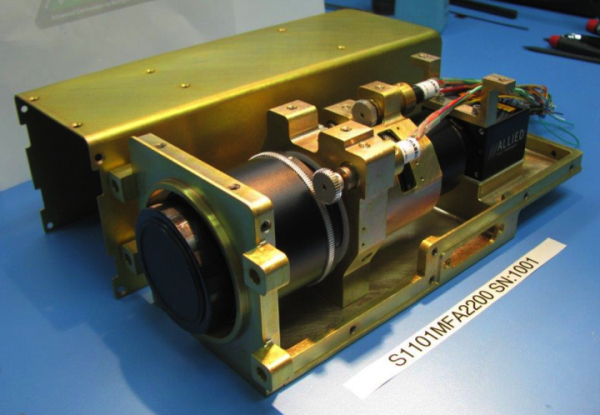
- The digital camera will be equipped with a filter assembly (shown below) with four options, where selection of a clear “filter” allows for color imaging.
- Color imaging can also be carried out with a blue-green BG7 Schott glass filter, which balances the color planes to avoid saturation in the red while maintaining sensitivity in the blue and green. The natural flame color can be approximately reconstructed, but the primary purpose of the filter is color-ratio pyrometry and measurement of the soot volume fraction.
- • Alternately, CH* imaging can be conducted with this camera because the filter assembly includes a 430-nm bandpass filter with a 10-nm full width at half-maximum transmission (FWHM). A 450-nm bandpass filter (again with a 10-nm FWHM) can be used with the CH* filter to effectively subtract interfering broadband soot emission. However, the filter assembly rotates slowly so such subtraction effectively requires a separate test with each filter and of course reproducible flame conditions.
OH* Imaging
- OH* is an excited (radical) molecule that emits light at 310 nm, which is in the ultraviolet, when it drops to a lower energy state in a process known as chemiluminescence.
- ACME will carry out OH* imaging using CIR’s Low-Light-Level Ultraviolet (LLL-UV) package, which is a monochrome camera with an intensifier (for 280-700 nm) and a 310-nm bandpass filter (with a 10-nm FWHM) for OH* imaging.
- As a result of the signal loss through the narrow bandpass filter, binning is employed such that the OH* images are recorded at 512×512 and 30 fps.
Color Ratio Pyrometry
- Pyrometry is a technique used to determine an object’s temperature from its broadband thermal radiation which is typically infrared but becomes visible at high temperatures. The yellow through red coloring of a typical hydrocarbon flame is caused by the glow of the hot soot particles, whereas the blue is related to the combustion chemistry (and is predominantly CH* emission). Yellow indicates a higher temperature than red, but a ratio of the light emitted at different wavelengths (or wavelength ranges) can be used to determine the temperature, but only where the soot is visibly glowing.
- Pyrometry can be accomplished with CIR’s monochrome High-Bit Depth Multispectral (HiBMs) camera, when equipped with a Liquid-Crystal Tunable Filter (LCTF) for imaging at multiple spectra. However, it requires a quasi-steady flame for measurement at each desired wavelength band.
- The HiBMs camera has a telecentric optical system and is recorded at 512×512 and 30 frames per second (fps). Although it has a 1024×1024 pixel array, binning has been necessary because of signal loss through the LCTF filter.
- * For soot-free flames, Thin Filament Pyrometry (TFP) can be used to determine the flame temperature. Ceramic fibers are stretched across the flame and glow when hot, just like the soot particles.
- ACME’s chamber insert is equipped with a crew-replaceable array of 5 silicon carbide (SiC) fibers. The TFP fibers are orthogonal to the flame axis and the array can be translated along the flame axis to the desired position downstream of the burner, e.g., based on the downlink of the analog video.
- * During set up, the crew can manually orient the TFP fiber array so that it is orthogonal to either the HiBMs camera with the LCTF or ACME’s digital color camera.
Temperature Measurement
- As a supplement to the pyrometry, the ACME chamber insert can accommodate six far-field thermocouples to measure the spread of the thermal field in the spherical flame experiments.
- The thermocouples are of limited utility for the other experiments because they are positioned upstream of the burner tip. Therefore, they will generally not be installed by the crew to reduce the chance of accidental damage.
- There will be two versions of a four-thermocouple rake to allow a choice of near and far measurements. Other arrays could be designed to support future experiments, but they cannot extend downstream of the burner tip without interfering with other (e.g., optical) measurements.
Soot Volume Fraction
- The amount of soot particulate in a flame can be determined via an extinction technique, where the camera and the collimated light source are positioned at opposite windows.
- For ACME, the extinction measurement will be made with a second High-Bit Depth Multispectral (HiBMs) camera, without a filter, in combination with CIR’s illumination package (with its two fiber-coupled laser diodes). The images are recorded at 1024×1024 and 30 frames per second.
- Alternatively, the soot volume fraction can be determined directly from the digital color camera, where an alternate Thin Filament Pyrometry (TFP) fiber array including a platinum wire will be used for inflight characterization for that measurement.
Thermal Radiation
- The ACME chamber insert includes a crew-exchangeable linear array of radiometers of which there are two versions supporting the initial set of experiments. Alternate arrays could be developed for future experiments.
- The radiometer array has a fixed position which is parallel to the chamber and burner axis and is centered (along the chamber length) relative to the chamber windows and thus most of the other instrumentation.
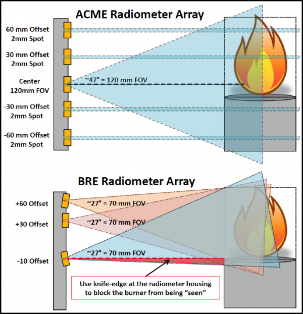
- An additional wide-view radiometer, that is fixed and not crew exchangeable, is positioned downstream of the burner and flame at 30o from the chamber axis. This detector is primarily intended to support the spherical flame experiments and will have a quicker response than the more sensitive detectors that will used in the linear arrays.
- • ACME’s radiometers are more precisely thermopile detectors with a spectral range of nominally 0.2-11 micron and fields of view that are established by appropriately selected apertures (i.e., rather than lenses).
Chemiluminescent Emission
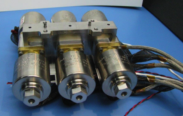
- To detect the quenching of dim flames, the chamber insert will be equipped with a set of three Photomultiplier Tube (PMT) modules.
- Each PMT will have a wide-angle view, a sight line that is orthogonal to the chamber axis, and will be centered (along the chamber length) relative to the chamber windows so that it is aligned with most of the other instrumentation.
- The PMTs’ spectral range will be 230-700 nm, i.e., visible and near ultraviolet, but one will have a 310-nm bandpass filter and another will have a 430-nm bandpass filter (where both are with a 10-nm FWHM). The filtered pair of detectors will enable measurement of OH* and CH* emission, respectively. The third PMT will be equipped with a neutral density filter to prevent saturation. Like many other ACME components, the PMT array can be removed from the chamber insert by the crew.
Other Measurements
- Additional supporting measurements will be made for the ACME experiments, where the chamber pressure is a simple example.
- The ACME experiments will use the CIR’s gas chromatograph for pre- and post-test analysis of the chamber atmosphere, e.g., for oxygen, nitrogen, carbon dioxide, carbon monoxide, and fuel gases.
- Acceleration measurements will be provided by the Space Acceleration Measurement System II (SAMS-II), which is the primary instrument for such measurements on ISS. Its predecessor previously served that role for the space shuttle.
Experiment-Unique Equipment
- Experiment-unique hardware is also mounted on the chamber insert. For example, to accommodate the E-FIELD Flames experiment, the insert is equipped with a high-voltage supply and a crew-removable electrode mesh which can be set between +10 and -10 kV. The circular mesh is orthogonal to the chamber axis and is positioned (during set up) at either ~35 or ~50 mm downstream of the insulated burner. The ion current between the burner and electrode mesh will be determined via measurement of the voltage drop across a known resistor and application of Ohm’s Law.
ACME Operations
- All ACME experiments will be constant volume (i.e., rather than constant pressure) studies, where the chamber’s free volume will be about 90 liters. Burner flows will generally be constrained to limit the pressure rise, and tests will typically be 0.5-2 minutes in duration.
- The ACME experiments will be configured, but not conducted, by the ISS crew. Instead, the experiments will be commanded from the ground, specifically from the Telescience Support Center (TSC) at the NASA Glenn Research Center.
- The ACME tests can be conducted in a nominally automated mode using pre-programmed scripts or in a “manual” mode where changes can be made (e.g., in the burner flow) in response to the analog video downlink and/or the numerical data available in the telemetry stream. The latter mode can facilitate the conduct of tests at or near limit conditions, e.g., for soot or stability.
Project Management
Project Manager: Lauren M. Brown, NASA Glenn Research Center
lauren.brown@nasa.gov
216-433-8429
Project Scientists: Dennis Stocker, NASA Glenn Research Center
Dennis.P.Stocker@nasa.gov
216-433-2166
Engineering Team: ZIN Technologies, Inc.