Cyclotron Operation

Cyclotrons accelerate charged particles and shoot them through a beam at a target which results in secondary fission that can be used for a variety of purposes. Cyclotrons rely on both electric and magnetic fields to accelerate the particles. A series of smaller magnets and focusing equipment refines the beam as it travels to its target.
Documents
Components
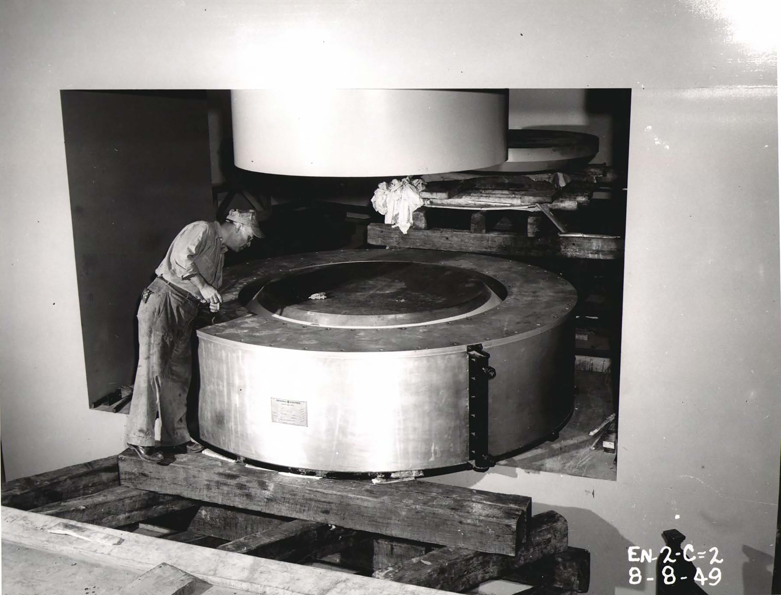
The primary components of a cyclotron are the magnetic system, vacuum-sealed dee chambers, oscillating power system, ion injector, and focusing equipment. The Lewis Cyclotron’s two large magnets were supported by a large rectangular frame, or yoke. The yoke’s forged steel slabs were 72 inches deep, 32 inches wide, and 84 (vertical) by 204 (horizontal) inches long.
This framework supported two cylindrical 72-inch-diameter and 30.5-inch-high magnetic poles. These poles were surrounded by two large circular coils that contained layers of wound copper wire and tubes for cooling water. The magnet system was powered a 250 volt motor generator and field exciter with a regulated electric current.
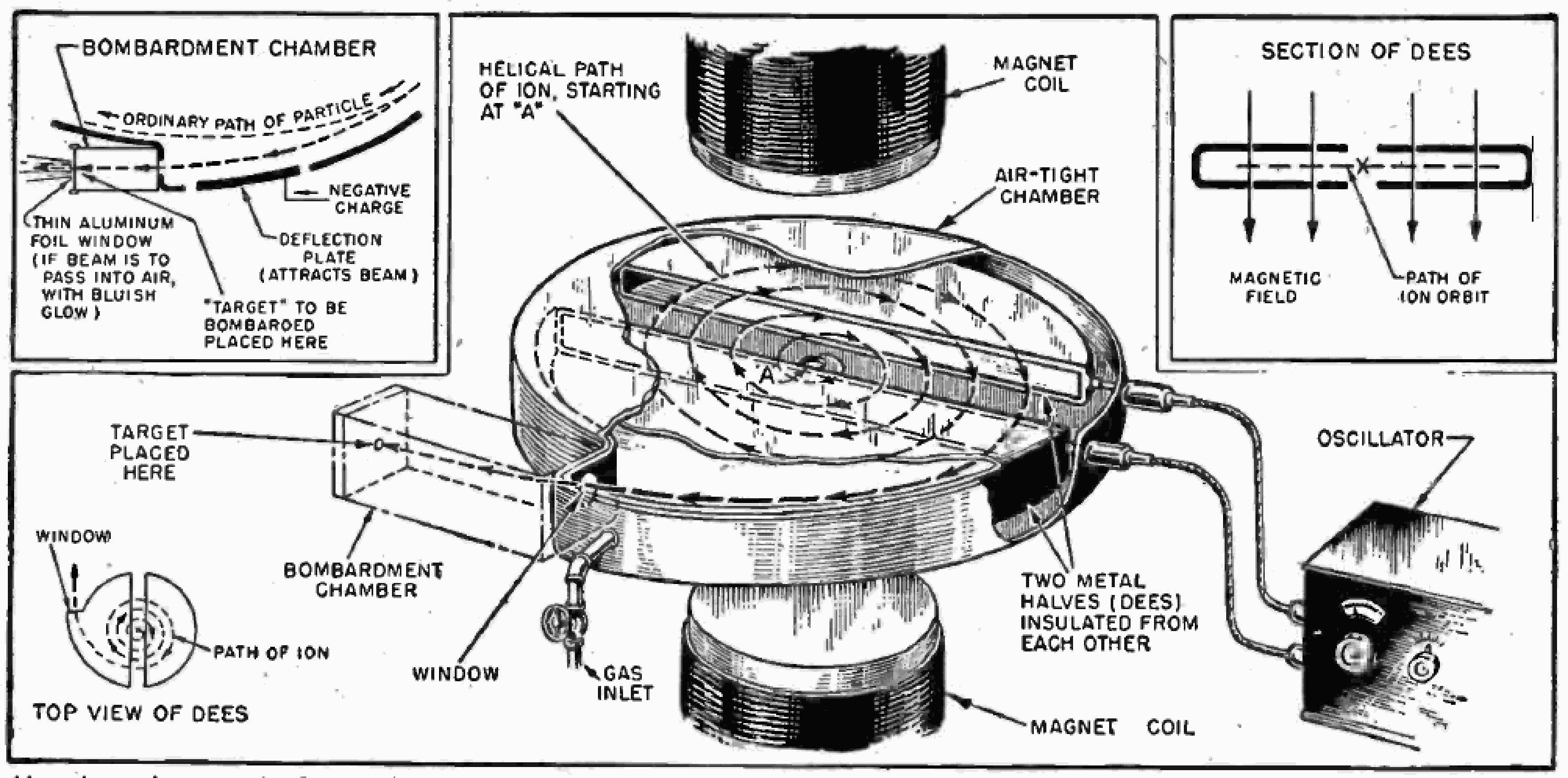
Two copper D-shaped electrodes, referred to as “dees,” were located perpendicularly between the two large magnets. The dees faced opposite one another forming a circle bisected by a narrow gap. Two pairs of triodes supplied oscillating radio frequency (RF) power to the gap.
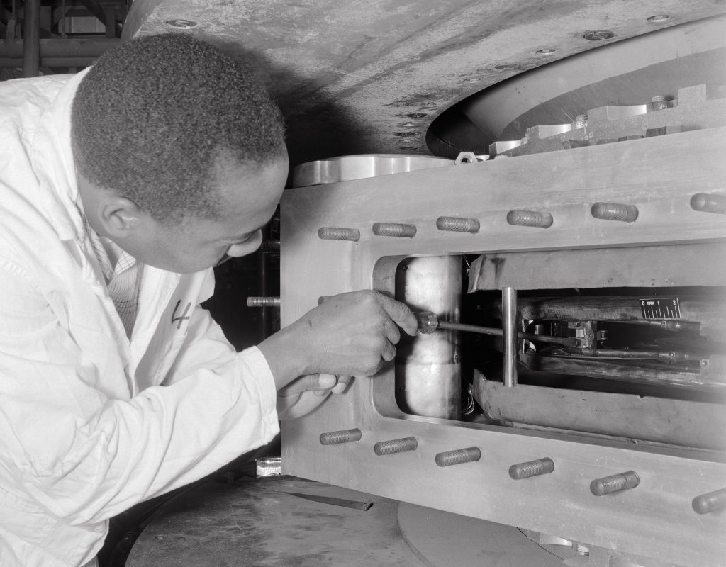
The dees were contained inside a vacuum chamber supported by several pumps and a refrigeration system and had moveable panels that permitted tuning the system.
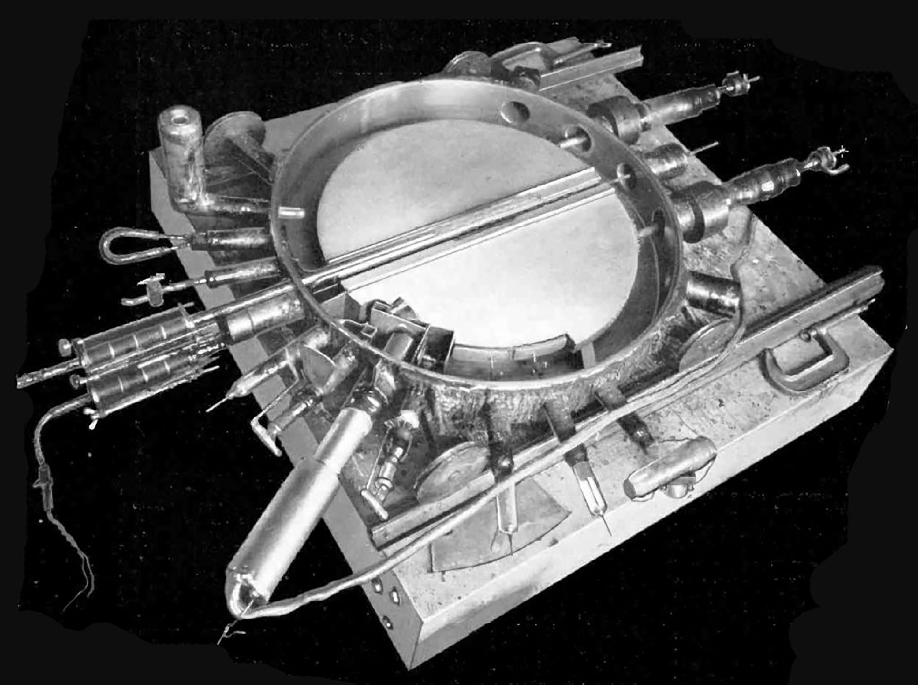
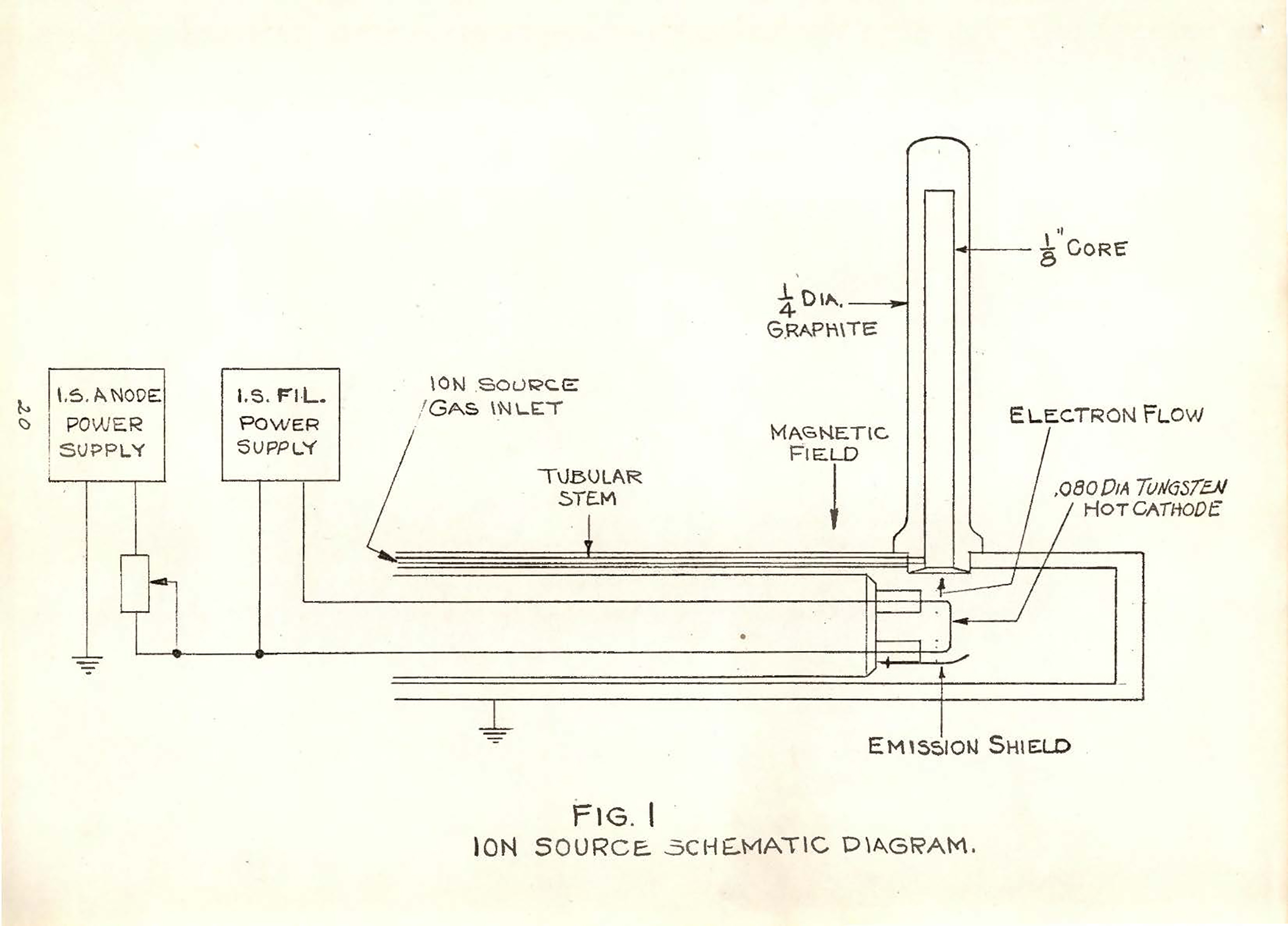
Above the top yoke was the arc chamber that produced charged particles, or ions, to be accelerated. The desired gas with uncharged particles—typically alpha particles, protons, or deuterons—was contained in the arc chamber along with an electric filament.
Activation of the filament produced an electric arc that charged the particles. The arc and filament could be adjusted from the control room to improve the quality of the particle beam.

Particle Acceleration
A stream of charged particles was then introduced into the dees through a hole drilled in the yoke and magnet. The vertical magnetic field was adjusted to guide the particle in a semi-circular route. The RF electric current was applied between the dees, which was rapidly alternated by an oscillator. As the particle reached the gap, the oscillator reversed the direction of current to accelerate the particle into the other dee.
Each pass over the gap increased the particle’s speed, which widened its orbit while maintaining the time it took to complete the circuit. Operators could increase the speed by adjusting the polarity of the electric field between the dees just before the particle appeared in the gap.
Once the particle reached the outer edge of the dee, it shot off into the beam deflector and out the exit window at high velocity. The deflector consisted of two arc-shaped pieces parallel to one another to guide the particle beam out. Operators in the control room could adjust the angle of the deflector to improve the quality of the beam.
Beam Control
The external beam equipment originally consisted of four components—the shield tube, focusing magnets, a beam-shaping diaphragm, and a deflector magnet. The beam emerged from the deflector horizontally about 4 feet from the floor. It first traveled through the 4-foot long shield tube to prevent the cyclotron’s electrical field from affecting the magnets. A chamber at the end of the tube contained a carbon disk to concentrate the beam.
The two adjustable focusing magnets then diverted the beam slightly. The beam was further concentrated as it passed through the vacuum-sealed diaphragm. The deflector magnet bent the beam horizontally at a 45° angle toward the Target Room. This equipment was frequently modified and expanded over the years.
The beam shutter target was a copper shutter used to fine tune the beam just before it struck the intended target. From the control room, operators made final adjustments to the cyclotron’s voltages or magnets. Once the desired parameters were met, the shutter was raised and the beam impacted the sample material.
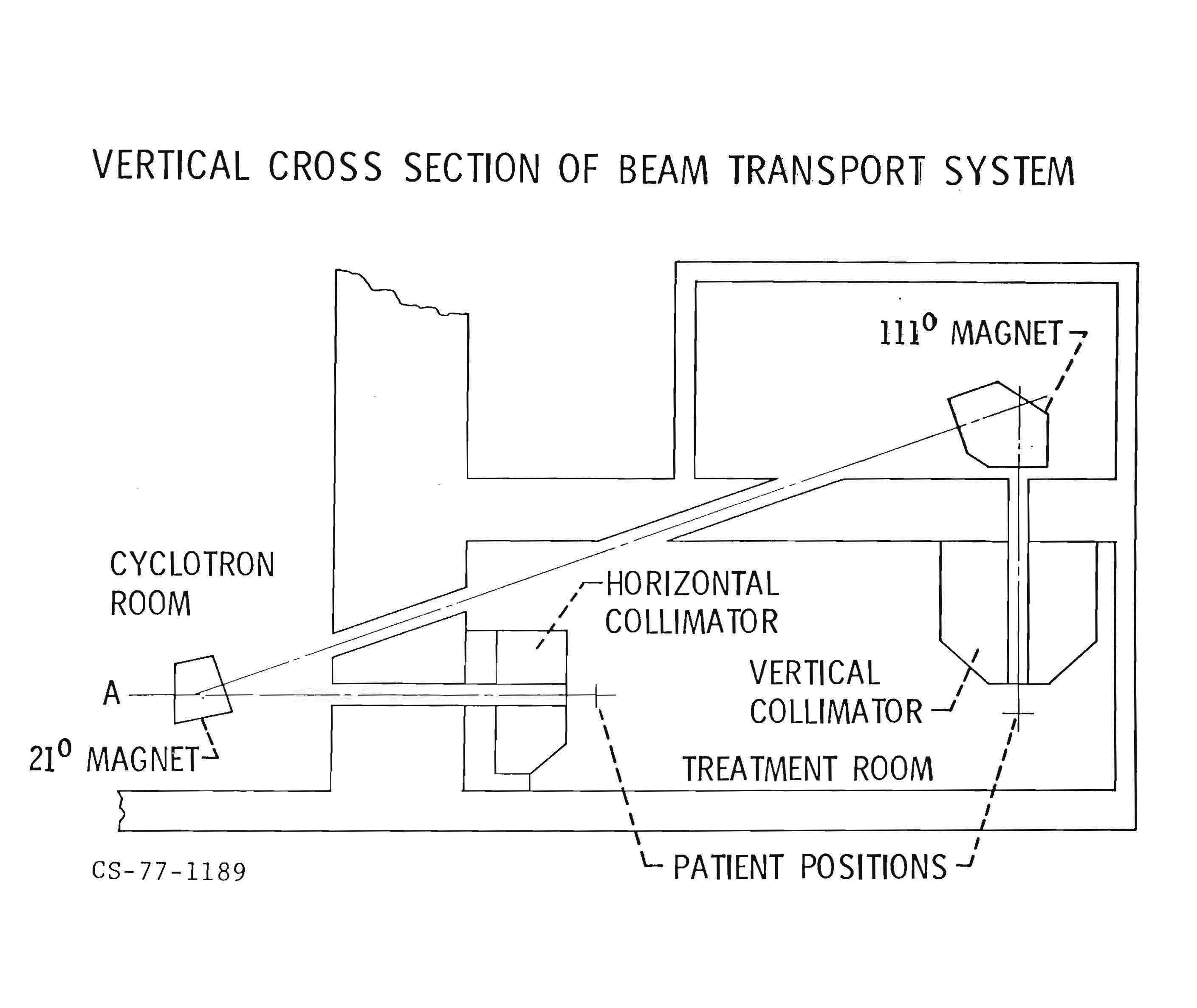
For the Neutron Therapy program in the 1970s, the beam was guided by three magnets to the beryllium target in a shielded apparatus. By inserting another magnet, the beam could be bent upward toward another set of magnets in the Magnet House above the Therapy Treatment Room. There the beam was then deflected downward into a beryllium target near the ceiling to produce vertical neutron beam.
Target Areas
The vacuum-sealed target chamber was installed in the Vault Room wall to facilitate the adjustment of target equipment without disrupting the environment within the Vault. The Vault side had a vacuum pivoting gate, and the Target Room side contained a flat aluminum shutter plate.
The cyclotron originally possessed two target assembly plates. One supported a channel and the other a foil window. The latter included three thin aluminum frames that allowed the beam pass through to strike the intended target.
The Neutron Therapy Room (former Target Room) contained a horizontal and vertical collimator that refined the fast neutrons before their application to patients. In both instances, the beryllium was shielded by at least 30 inches of Benelex, a plastic composite.
The one eighteenth of an inch thick beryllium target was located behind an aperture to make sure the beam struck the target correctly. The neutrons then passed through an ion chamber that measured the stream before it reached the patient.
Safety Measures
They cyclotron generated high levels of radiation that could cause health problems, but was mostly short lived. The Vault Room, Skylight Room, Hot Storage Room, and the hallway leading to the Target Room were regularly exposed to radiation. The Cyclotron Facility utilized radiation monitors in the Vault Room and hallways to track levels. Personnel were also required to wear dosimeters and survey meters to track their exposure.
The particle beam was automatically disabled if doors to the Vault Room or Target Room were opened or if sensors detected motion in the hallway. There were also mechanisms in the Target Room and Vault Room for individuals to stop the beam if it engaged while they were present.
Activities at the Cyclotron Facility were tightly controlled by documented procedures and safety manuals. These were overseen by the center’s Radiation Safety Committee, which was composed of senior managers with extensive technical expertise in the areas of health physics and radiation protection.