Effects of Shape on Lift Interactive
Lift Coefficient
The amount of lift generated by a wing depends on how much the flow is turned, which depends on the shape of the object. The lift is, in general, a very complex function of the shape. Aerodynamicists model the effect by a lift coefficient which is normally determined through wind tunnel testing. The Wright brothers built a wind tunnel in 1901 to determine the best shape for their wings. One simple result of their testing showed that the greater the flow turning, the greater the lift. You can investigate the effects of shape on lift by using a computer simulation of the Wright’s 1901 tunnel.
Airfoil
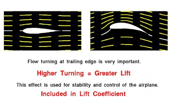
This slide shows the flow fields for two different modern airfoils. The airfoil on the left is a symmetric airfoil; the shapes above and below the white centerline are the same. The airfoil on the right is curved near the trailing edge. The yellow lines on each figure show the streamlines of flow from left to right. The left figure shows no net turning of the flow and produces no lift; the right figure shows a large amount of turning and generates a large amount of lift. The front portions of both airfoils are nearly identical. The aft portion of the right airfoil creates the higher turning.
This explains why the aft portion of modern wings have hinged sections, and why the Wrights used wing warping to control and maneuver their aircraft. Deflecting the aft section down will produce a geometry similar to the figure on the right producing more lift. Similarly, if the aft section is deflected up, it will create less lift (or even negative lift). The ability to vary the amount of lift over a portion of the wing gives the pilot the ability to maneuver an aircraft. The following pages show the deflection of the control surfaces and the resulting motion of the Wright 1902 aircraft, the first aircraft to be controlled about all three axes.
- Elevator controls pitching motion.
- Rudder controls yawing motion.
- Wing Warping control rolling motion.
You can investigate the dependence of lift on airfoil shape by using this JavaScript program.
Please note: the simulation below is best viewed on a desktop computer. It may take a few minutes for the simulation to load.
Instructions
You can vary the shape of the foil by using the slider below the view window or by backspacing over the input box, typing in your new value and hitting the Enter key on the keyboard. On the right is a graph of the lift versus camber. The red dot shows your conditions. Below the graph is the numerical value of the lift. You can display either the lift value (in English or Metric units) or the lift coefficient by using the choice buttons surrounding the output box. Click on the choice button and select from the drop-menu.
As an experiment, set the camber to 0.0 per cent chord and note the amount of lift. Now increase the camber to 5 per cent. Did the lift increase or decrease? Set the camber to -5 per cent. What is the value of lift? Which way would this airfoil move?
The original source code for the simulations is available for users to download at the BGA Simulations on GitHub.