Drag Measurement
Wind Tunnels
Aerodynamicists use wind tunnels to test models of proposed aircraft and engine components. During a test, the model is placed in the test section of the tunnel and air is made to flow past the model. Various types of instrumentation are used to determine the forces on the model. The most basic type of instrument is the force balance.
Use of Force Balance
Force balances are used to directly measure the aerodynamic forces and moments on the model. On this page, we will discuss the measurement of the drag force to demonstrate the basic principles involved with force balances. This configuration is called a one component balance since it only measures one force. There are more sophisticated, three-component balances that can simultaneously measure lift, drag and pitching moment. A six-component balance is required to measure all three forces (lift, drag, and side) and three moments (pitch, roll, and yaw) that determine a rocket’s motion through the air.
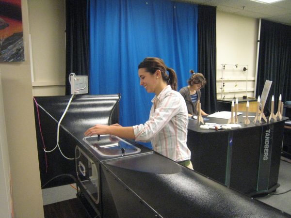
In the figure, we see a picture of the Wright Memorial Tunnel (WMT) at the NASA Glenn Research Center. The WMT is used for student projects and as a travelling exhibit to let the public see how wind tunnels operate. The top speed in the test section is about 50 mph. Here is a more detailed picture showing a rocket model mounted in the test section of the tunnel.
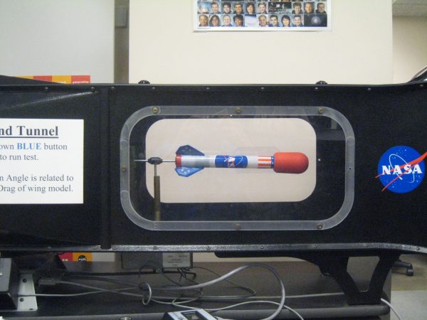
The model is mounted on a sting attached to the base of the rocket. The left part of the sting passes through the bottom wall of the tunnel and attaches to a strain gage on the outside of the tunnel. The strain gage is contained in the silver box located under the test section of the wind tunnel. Output from the strain gage is fed to a transducer that converts the measurements into drag data that is displayed on a laptop computer. During testing, the angle of attack of the rocket is varied to produce a performance curve for the model. A variety of models with different shapes were tested in the tunnel. These models can be seen on the table at the right of the upper figure. After wind tunnel testing, the data was curve fit and is now made available in the RocketModeler III computer program.
Determining Drag
This method of determining drag requires an electronic strain gage and a laptop computer to convert the electronic output into units of force. To accurately determine the aerodynamic forces and moments on a rocket model in a “real” wind tunnel requires even more sophisticated instrumentation and larger computer systems for data reduction and display. Multiple electronic strain gages are often placed inside the model, or on a measuring platform outside the tunnel. Multiple gages permit the determination of multiple forces and moments during the same test.
Some student-built wind tunnels are equipped with much simpler mechanical methods to measure lift and drag. In place of the electronic strain gage, a simple spring scale can be used if the forces are small. In either case, the instruments must be calibrated against a known amount of force before and during a wind tunnel test.