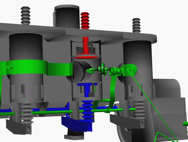
Combustion Chamber
This is a computer drawing of a combustion chamber of the Wright brothers’ 1903 aircraft engine. This engine powered the first, heavier than air, self-propelled, maneuverable, piloted aircraft; the Wright 1903 Flyer, flown at Kitty Hawk, North Carolina, in December 1903. To generate thrust for their aircraft, the brothers used twin, counter-rotating propellers at the rear of the aircraft. To turn the propellers, the brothers designed and built a water-cooled, gasoline powered, four-stroke, four-cylinder, internal combustion engine.
The figure at the top shows the major components of a combustion chamber on the Wright 1903 engine. In any internal combustion engine, fuel and oxygen are combined in a combustion process to produce the power to turn the crankshaft of the engine. The combustion takes place in the combustion chamber. There is a combustion chamber for each cylinder of the engine.
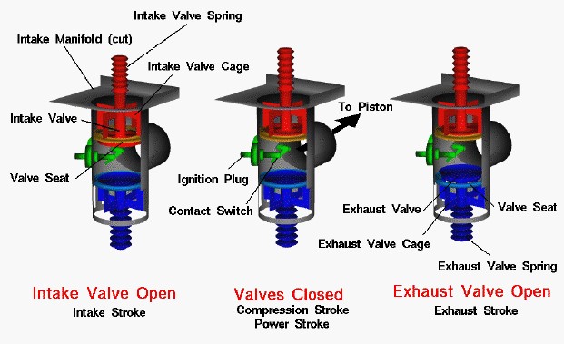
On the figure we show cylinder #4 at three different times during the engine cycle. We have peeled open the side of the chamber and the intake manifold which sits on top of the chamber, and we have color coded the parts for easy identification. The figure on the left shows the parts during the intake stroke of the cycle. The intake valve (red) is normally held snug against the valve seat (yellow) by the intake valve spring. The seat and the edge of the valve are carefully machined so that gases cannot pass between them when the valve is closed.
During the intake stroke, the intake valve is pulled open, and a small gap exists between the valve and the seat. Fuel and air in the intake manifold flows through the gap and into the combustion chamber. The valve can only move up and down because the intake valve cage holds the stem of the valve.
The middle figure shows the parts during the compression and power strokes of the cycle. The intake valve is now closed, and the chamber forms a totally closed vessel with the piston and cylinder. Protruding through the walls of the chamber are the ignition plug (green) and contact switch. The switch is normally held open. The switch is closed against the plug and opens quickly to generate a spark to ignite the fuel/air mixture during the combustion process.
The figure on the right shows the parts during the exhaust stroke. The exhaust valve (blue), like the intake valve, is normally held snug against its valve seat by the exhaust valve spring. During the exhaust stroke, the valve is pushed open by a cam-driven rocker arm. Like the intake valve, the exhaust valve is held in place by a valve cage which wraps around the valve stem. When the exhaust valve is opened, the hot exhaust gas is pushed through the open valve and exits the engine.
The movement of all these parts is coordinated by the timing system and is shown in this animation: