Winglets
Factors of Aerodynamic Drag
There are many factors which influence the amount of aerodynamic drag which a body generates. Drag depends on the shape, size, and inclination, of the object, and on flow conditions of the air passing the object. For a three dimensional wing, there is an additional component of drag, called induced drag, or drag due to lift. Induced drag is a three dimensional effect related to the distribution of lift across the wing. Flow near the wing tips have a strong influence on the amount of induced drag because of the tip vortices that are generated there. The aspect ratio is the ratio of the square of the span to the wing area. Induced drag is inversely related to the aspect ratio of the wing. Long thin wings have low induced drag. Wings with an elliptical planform also have lower induced drag than rectangular wings, as expressed in the efficiency factor in the induced drag equation. The outstanding aerodynamic performance of the British Spitfire of World War II is partially attributable to its elliptic shaped wing which gave the aircraft a very low amount of induced drag.
Winglets
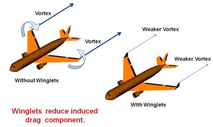
For many years, wing designers have attempted to reduce the induced drag component by special shaping of the wing tips. The Wright Brothers used curved trailing edges on their rectangular wings based on wind tunnel results. On modern airliners, the wing tips are often bent up to form winglets. Winglets were wind tunnel tested and computer analyzed by Richard Whitcomb of the NASA Langley Research Center in the mid 1970’s. The idea behind the winglet is to reduce the strength of the tip vortex and therefore cause the flow across the wing to be more two-dimensional. Flight tests at the NASA Dryden Flight Research Center have found a 6.5% reduction in the fuel use of a Boeing 707 type airliner when using winglets. Winglets must be carefully integrated into the total wing design, which explains why many different winglet designs appear on various airliners.
Effects of Induced Drag
There is a mathematical equation that quantifies the effects of induced drag. For a wing, the total drag coefficient, Cd is equal to the base drag coefficient at zero lift Cdo plus the induced drag coefficient Cdi.
\(\LARGE C_d = C_{do} + C_{di}\)
Drag Coefficient
The drag coefficient in this equation uses the wing area for the reference area. Otherwise, we could not add it to the square of the lift coefficient, which is also based on the wing area.
The induced drag coefficient Cdi is equal to the square of the lift coefficient Cl divided by the quantity: pi (3.14159) times the aspect ratio AR times an efficiency factor e. The value of the efficiency factor is 1.0 for an elliptical wing and some smaller number for any other planform. The value is about .7 for a rectangular wing.
\(\LARGE C_{di} = \frac{C_l^2}{\pi*AR*e}\)
Wing Area
The aspect ratio is the square of the span s divided by the wing area A.
\(\LARGE AR=\frac{s^2}{A}\)
Wing Chord
For a rectangular wing this reduces to the ratio of the span to the chord c.
\(\LARGE AR (rectangle) = \frac{s}{c}\)
Wind Tunnel Tests
To help you understand the effects of winglets on the drag of a wing, we have performed some simple wind tunnel tests with a variety of winglet models. The winglet design, construction, and testing was performed by three high school “shadows”. The wind tunnel that was used is a low speed tunnel that has been used for several student projects. The winglets were attached to a 1/72 scale model of a Cessna 172. Five different winglet configurations were wind tunnel tested in May, 2014, by Austin Vorisek, a graduate of Solon High School, who will be attending Ohio State University in the fall of 2014, and Alex Mann, a graduate of Orange High School, who will be attending Akron University in the fall of 2014. An additional nine configurations were studied in June, 2014, by Dominic Roberts II, a home-schooled senior from Lansing, Michigan, who is already working at the aero lab at Michigan State University.
Wing Design
The students prepared this small Java computer program to display the experimental results. Simply select the wing design from the drop menu. The design of the winglet as viewed from the side will be shown at the far right. Enter the drag coefficient for the wing without winglets at the left and the program will calculate a change to the drag coefficient with winglets. Some winglet designs have little or no effect, some actually make the drag worse because they increase the overall surface area of the aircraft model. But some of the models do produce an effect in the correct range as indicated by the flight tests described above. Entering the speed, altitude, and wing area provides the program with enough data to calculate the drag of the wing. As a naming convention, “SW” denotes single winglet pointing up from the wing, “DW” is a double winglet; one pointing up and one pointing down.