Vector Balance of Forces – Glider
Balance of Forces
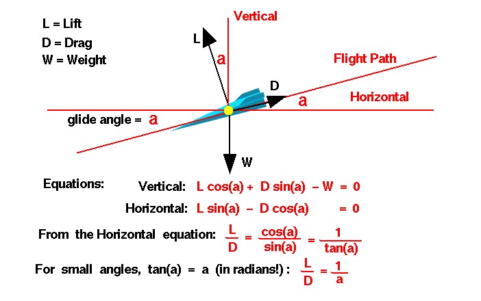
This slide shows the balance of forces on a descending glider. There are three forces acting on the glider; weight, lift, and drag. Forces are vector quantities having both a magnitude and a direction. The magnitude of the weight is given by the weight equation and depends on the mass of the aircraft and its payload. The direction of the weight is always towards the center of the earth. On the figure, the direction is along the vertical axis, pointed towards the bottom of the figure. The magnitude of the lift is given by the lift equation and depends on several factors. The lift is directed perpendicular to the flight path which is shown as a thin red line which fall to the left on the figure. The magnitude of the drag is given by the drag equation and depends on factors associated with the design. The drag is directed along the flight path opposed to the motion. A horizontal, thin red line has been drawn parallel to the ground and through the center of gravity of the glider. The flight path of the glider crosses the horizontal at an angle a called the glide angle. Using some geometry theorems on angles, perpendicular lines, and parallel lines, we see the glide angle “a” also defines the angle between the lift and the vertical, and between the drag and the horizontal.
Vector Component Equations
Assuming that the forces are balanced (no acceleration of the glider), we can write the two vector component equations for the forces. In the vertical direction, the lift L times the cosine cos of the glide angle a plus the drag D times the sine sin of the glide angle minus the weight W equals zero:
\(\LARGE Vertical: L * cos(a) + D * sin(a) – W = 0\)
In the horizontal direction, the lift times the sine of the glide angle minus the drag times the cosine of the glide angle equals zero:
\(\LARGE Horizontal: L * sin(a) – D * cos(a) = 0\)
Rearranging the horizontal component equation:
\(\LARGE L * sin(a) = D * cos(a)\)
\(\LARGE \frac{L}{D} = \frac {cos(a) }{sin(a)}=\frac{1}{tan(a)}\)
gives the relation that the lift divided by the drag is equal to the cosine of the glide angle divided by the sine of the glide angle. This ratio of trigonometric functions is equal to the cotangent of the angle, or the inverse of the tangent of the glide angle. For small angles, the tangent of the angle is almost the value of the angle in radians. This gives us the following relationship:
\(\LARGE \frac{L}{D}= \frac{1}{a}\)
the lift divided by the drag is equal to the inverse of the glide angle for small angles.
L/D Ratio
What good is all this for aircraft design? The lift divided by drag is called the L/D ratio and is an efficiency factor for aircraft. From the last equation we see that the higher the L/D, the lower the glide angle. The glide angle determines how far a glider will fly horizontally for each vertical foot (or meter) that it falls. The lower the glide angle, the farther the glider can fly. Therefore, designers of long distance gliders want a high L/D. We can also use measurements of the glide angle and weight of the glider to determine the L/D ratio as shown on another page.