Power Train

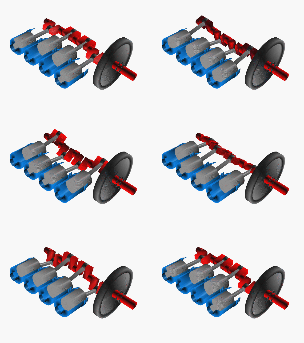
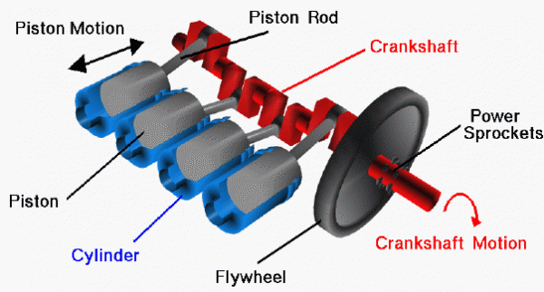
This is a computer animation of the power train of the Wright brothers’ 1903 aircraft engine. This engine powered the first, heavier than air, self-propelled, maneuverable, piloted aircraft; the Wright 1903 Flyer, flown at Kitty Hawk, North Carolina, in December 1903. To generate thrust for their aircraft, the brothers used twin, counter-rotating propellers at the rear of the aircraft. To turn the propellers, the brothers designed and built a water-cooled, gasoline powered, four-stroke, four-cylinder, internal combustion engine. In this animation, and on the figure below, we have stripped away all of the engine parts except those associated with the power train. The view is from above the rear of the engine.
As the name implies, the job of the power train is to provide the power to turn the aircraft propellers. For the brothers’ propulsion system, two power sprockets are located on a rotating crankshaft, colored red, which turns large “bicycle” chains to power the propellers. The energy to rotate the crankshaft is provided during the power stroke of four pistons, colored gray, moving in enclosed cylinders, colored blue. The power train converts the linear motion of the pistons into rotational motion of the crankshaft. There are three main parts to the power train: the crankshaft, the pistons, and the cylinders.

The crankshaft is a single, long piece of metal which is cut into a very specific “snake” shape. The ends of the shaft are rounded to accept the flywheel and the sprockets at the right of the figure, and the timing sprocket on the left end. The three rounded sections in the middle of the crankshaft ride on bearings in the crankcase of the engine. There are four additional rounded sections of the crankshaft which are enclosed by the ends of the piston rods. The piston rods are connected to the pistons by pins which you can’t see in this view.
Four combustion chambers are connected to the opened ends of the cylinders, to the left in the figure. During the combustion of the fuel, the pressure is increased in the combustion chamber and in the volume formed by the piston head and the top of the cylinder. The pressure on the head of the cylinder generates the force to move the piston and the crankshaft. The pistons fire one at a time in a specified order. The job of the flywheel is to store the energy from the individual firings so that the engine runs more smoothly.
