Modern Drag Equation
Between 1900 and 1905, the Wright brothers designed and built three unpowered gliders and three powered aircraft. As part of the design process, they had to make some mathematical estimates of the lift and drag of their vehicles. The Wright brothers were bicycle mechanics and had a good working knowledge of math and science. They knew about Newton’s laws of motion and about forces. They knew that they needed to generate enough aerodynamic lift to overcome the weight of their aircraft. They were also aware of mathematical equations which could be used to predict the amount of lift and drag that an object would generate.
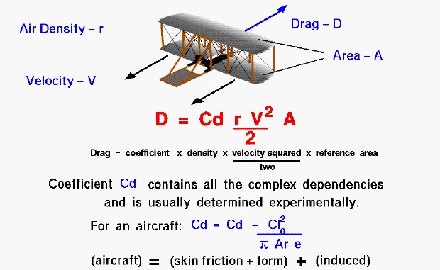
On this page we present the modern version of the drag equation. The amount of drag generated by an object depends on a number of factors, including the density of the air, the velocity between the object and the air, the viscosity and compressibility of the air, the size and shape of the body, and the body’s inclination to the flow. The drag equation states that drag (D) is equal to a drag coefficient (Cd) times the density of the air (r) times half of the square of the velocity (V) times the wing area (A).
D = .5 * Cd * r * V^2 * A
In general, the dependence on body shape, inclination, air viscosity, and compressibility is very complex. One way to deal with complex dependencies is to characterize the dependence by a single variable. For drag, this variable is called the drag coefficient, designated “Cd”. At the time of the Wright brothers, the drag coefficient was usually referenced to the drag of a flat plate of equal projected area. On another page we show some typical values for the drag coefficient. For the Wright’s aircraft, the basic drag coefficient was equal to about .045.
For given air conditions, shape, and inclination of the object, we have to determine a value for Cd to determine the drag. The drag coefficient is composed of two parts; a basic drag coefficient which includes the effects of skin friction and shape (form), and an additional drag coefficient related to the lift of the aircraft. The additional source of drag is called the induced drag and it is produced at the wing tips due to aircraft lift. Because of pressure differences above and below the wing, the air on the bottom of the wing is drawn onto the top near the wing tips. This creates a swirling flow which changes the effective angle of attack along the wing and “induces” a drag on the wing. The induced drag coefficient is equal to the square of the lift coefficient (Cl) divided by the quantity: pi (3.14159) times the aspect ratio (Ar) times an efficiency factor (e). The aspect ratio is the square of the span divided by the wing area. For a rectangular wing this reduces to the ratio of the span to the chord. Long, slender, high aspect ratio wings have lower induced drag than short, thick, low aspect ratio wings. Lifting line theory shows that the optimum (lowest) induced drag occurs for an elliptic distribution of lift from tip to tip. The efficiency factor (e) is equal to 1.0 for an elliptic distribution and is some value less than 1.0 for any other lift distribution. For a rectangular planform, like the Wright brothers wings, e = .7 . The total drag coefficient is equal to the drag coefficient at zero lift (Cdo), plus the induced drag coefficient.
Cd = Cd0 + Cl^2 / ( pi * Ar * e)
The Wright brothers learned about induced drag the hard way. Following their first glider flights of 1900, they knew that they had to increase the size of their wings to allow flight in reasonable winds. For the 1901 aircraft they increased the chord of the wing but kept the span nearly the same. This produced a wing with an aspect ratio of 3.0 and high induced drag. The brothers had made mathematical predictions of the performance of their aircraft. But the 1901 aircraft did not meet their range predictions because of lower than expected lift and higher than expected drag. During the winter, with the aid of their wind tunnel, they began to understand the role of induced drag on their aircraft’s poor performance. They then designed the 1902 aircraft wing to have a longer span and shorter chord than the 1901 aircraft. The aspect ratio was changed to 6.0 with nearly the same wing area. By doubling the aspect ratio, the brothers cut the induced drag in half. The 1902 aircraft was able to meet their performance goals and they were able to attain glides of over 650 feet.
Remember that determining the drag is only a part of the design problem. You will find that a higher angle of attack produces more lift, but it also produces more drag. You will also find that increasing the wing area increases the lift. But in the total design, increasing wing area also increases the weight and the drag. Designers usually try to optimize the lift to drag ratio. This is an efficiency factor for the aircraft and inversely related to the glide angle. An aircraft with a high lift to drag ratio can glide a long distance while losing only a little altitude. The Wrights were aware that they needed both high lift and low drag.