Heat Rejection
This is a computer drawing of one cylinder of the Wright brothers’ 1903 aircraft engine. This engine powered the first, heavier than air, self-propelled, maneuverable, piloted aircraft; the Wright 1903 Flyer. The engine consisted of four cylinders like the one shown above, with each piston connected to a common crankshaft which turns the propellers to produce thrust.
The brothers’ design is very simple by today’s standards, so it is a good engine for students to study to learn the fundamentals of engine operation. This type of internal combustion engine is called a four-stroke engine because there are four movements (strokes) of the piston before the entire engine firing sequence is repeated. In the figure, we have colored the fuel/air intake system red, the electrical system green, and the exhaust system blue. We also represent the fuel/air mixture and the exhaust gases by small colored balls to show how these gases move through the engine. Since we will be referring to the movement of various engine parts, here is a figure showing the names of the parts:
Mechanical Operation
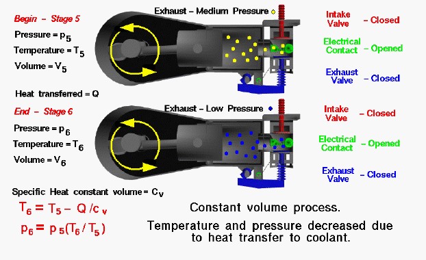
At the end of the power stroke the exhaust has been expanded into the cylinder to a moderate pressure and temperature by the motion of the piston to the left. From our considerations of the engine cycle, we designate this condition as Stage 5 of the Otto cycle. The intake valve and exhaust valve are closed and the electrical contact is open. The exhaust has done work on the piston but there is some residual heat in the exhaust gas. As the piston comes to a halt near the crankshaft, the residual heat is quickly transferred to the water in the water jacket surrounding the cylinder. In theory, the transfer proceeds so quickly that we can consider the piston to be motionless and the volume of the combustion chamber and cylinder to be a constant. The end of the heat rejection process is designated Stage 6 of the engine cycle and is the beginning of the exhaust stroke.
Thermodynamics
Because the intake and exhaust valves are closed, the heat transfer from the exhaust gas takes place in a nearly constant volume vessel. The heat transfer decreases the temperature of the exhaust gas. From considerations of the first law of thermodynamics, the temperature decrease is given by:
\(\LARGE T_6=T_5-\frac Q{cv}\)
where Q is the heat rejected, T is the temperature, and cv is the specific heat at constant volume, From the equation of state, we know that:
\(\LARGE p_6=p_5\cdot\frac{T_6}{T_5}\)
where p is the pressure. The numbers indicate the two stages of the cycle. Since Q is a positive number, T6 is less than T5 and p6 is less than p5. Temperature and pressure in the cylinder both decrease during the cooling process. The final value of the pressure is atmospheric pressure and this determines the amount of heat that is rejected. In theory, the heat transfer takes place instantaneously when the piston is motionless. In reality, the heat is transferred throughout the exhaust stroke. The effect is the same, but reality is so much harder to analyze that we make the assumption of instantaneous heat release to obtain an initial estimate of the heat transferred.