Drag Coefficient
Drag Coefficient
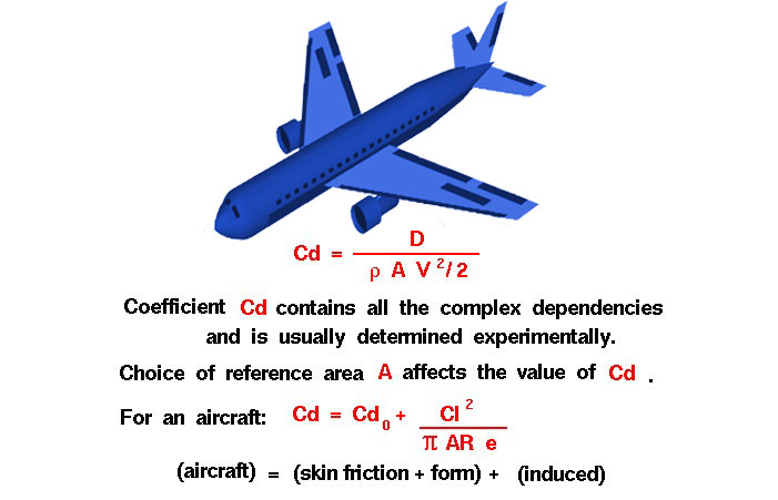
The drag coefficient is a number that engineers use to model all of the complex dependencies of shape, inclination, and flow conditions on aircraft and rocket drag. This equation is simply a rearrangement of the drag equation where we solve for the drag coefficient in terms of the other variables. The drag coefficient Cd is equal to the drag D divided by the quantity: density ρ times half the velocity V squared times the reference area A.
\(\LARGE C_d=\frac{D}{\frac{\rho\cdot A\cdot V^{2}}{2}}\)
The quantity one half the density times the velocity squared is called the dynamic pressure q. So
\(\LARGE C_d=\frac D{q\cdot A}\)
The drag coefficient then expresses the ratio of the drag force to the force produced by the dynamic pressure times the area.
Determining Value for Drag Coefficient
This equation gives us a way to determine a value for the drag coefficient. In a controlled environment like a wind tunnel we can set the velocity, density, and area and measure the drag produced. Through division we arrive at a value for the drag coefficient. As pointed out on the drag equation slide, the choice of reference area (frontal area or surface area) will affect the numerical value of the drag coefficient that is calculated. When reporting drag coefficient values, it is important to specify the reference area that is used to determine the coefficient. We can predict the drag that will be produced under a different set of velocity, density (altitude), and area conditions using the drag equation.
Air Viscosity and Compressibility Effects
The drag coefficient contains not only the complex dependencies of object shape and inclination, but also the effects of air viscosity and compressibility. To correctly use the drag coefficient, we must be sure that the viscosity and compressibility effects are the same between our measured case and the predicted case. Otherwise, the prediction will be inaccurate. For very low speeds (< 200 mph) the compressibility effects are negligible. At higher speeds, it becomes important to match Mach numbers between the two cases. Mach number is the ratio of the velocity to the speed of sound. At supersonic speeds, shock waves will be present in the flow field and we must be sure to account for the wave drag in the drag coefficient. So it is completely incorrect to measure a drag coefficient at some low speed (say 200 mph) and apply that drag coefficient at twice the speed of sound (approximately 1,400 mph, Mach = 2.0). It is even more important to match air viscosity effects. The important matching parameter for viscosity is the Reynolds number that expresses the ratio of inertial forces to viscous forces. In our discussions on the sources of drag, recall that skin friction drag depends directly on the viscous interaction of the object and the flow. If the Reynolds number of the experiment and flight are close, then we properly model the effects of the viscous forces relative to the inertial forces. If they are very different, we do not correctly model the physics of the real problem and will predict an incorrect drag.
Flow Conditions
The drag coefficient equation will apply to any object if we properly match flow conditions. If we are considering an aircraft, we can think of the drag coefficient as being composed of two main components; a basic drag coefficient which includes the effects of skin friction and shape (form), and an additional drag coefficient related to the lift of the aircraft. This additional source of drag is called the induced drag or drag due to lift. Induced drag occurs because of the distribution of lift across the span of the wing. Because of pressure differences above and below the wing, the air on the bottom of the wing is drawn onto the top near the wing tips. This creates a swirling flow which changes the effective angle of attack along the wing and “induces” a drag on the wing. The induced drag coefficient Cdi is equal to the square of the lift coefficient Cl divided by the quantity: pi (π) (3.14159) times the aspect ratio AR times an efficiency factor e.
\(\LARGE C_{di}=\frac{Cl^2}{\mathrm\pi\cdot AR\cdot e}\)
The aspect ratio is the square of the span s divided by the wing area A.
\(\LARGE AR=\frac{s^2}A\)
Aspect Ratio Wings
For a rectangular wing this reduces to the ratio of the span to the chord. Long, slender, high aspect ratio wings have lower induced drag than short, thick, low aspect ratio wings. Lifting line theory shows that the optimum (lowest) induced drag occurs for an elliptical distribution of lift from tip to tip. The efficiency factor e is equal to 1.0 for an elliptical distribution and is some value less than 1.0 for any other lift distribution. A typical value for e for a rectangular wing is .70 . The outstanding aerodynamic performance of the British Spitfire of World War II is partially attributable to its elliptic shaped wing which gave the aircraft a very low amount of induced drag. The total drag coefficient Cd is equal to the drag coefficient at zero lift Cdo plus the induced drag coefficient Cdi.
\(\LARGE C_d=C_{d0}+C_{di}\)
The drag coefficient in this equation uses the wing area for the reference area. Otherwise, we could not add it to the square of the lift coefficient, which is also based on the wing area.