Crankcase

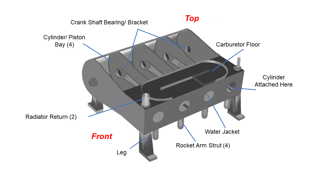
This is a computer drawing of the crankcase of the Wright brothers’ 1903 aircraft engine. This engine powered the first, heavier than air, self-propelled, maneuverable, piloted aircraft; the Wright 1903 Flyer, flown at Kitty Hawk, North Carolina, in December 1903. To generate thrust for their aircraft, the brothers used twin, counter-rotating propellers at the rear of the aircraft. To turn the propellers, the brothers designed and built a water-cooled, gasoline powered, four-stroke, four-cylinder, internal combustion engine.
The crankcase is the “body” that holds all of the other engine parts together. It’s the largest part of the engine but must be designed to be both strong and light. To keep the weight low, the brothers used aluminum to make the crankcase. The crankcase was cast at a foundry in Dayton. In this process, a mold of the crankcase is made (using sand or other materials), and hot, liquid aluminum is poured into the mold and allowed to cool into a solid, shaped piece.
You can see that the piece was fairly intricate, with a number of holes and webs. Four legs were cast into the crankcase on the corners to attach the engine to the lower wing of the aircraft. Looking at the figure in a little more detail, there are two main parts to the crankcase, a box-like structure to the right and a curved structure to the left as viewed from the front of the engine.
Cylinders, Radiator, and Carburetor
As viewed from the front, the box-like structure to the right of the crankcase holds the four cylinders. The cylinders are screwed from inside the box into the holes facing to the right. The combustion chambers are then screwed into the cylinders from outside the box. The rocker arm struts hold the rocker arms which open the exhaust valves of the combustion chambers. Additional castings on the bottom hold the camshafts and the lubrication system.
The box structure also holds the water used to cool the cylinders in an arrangement called a water jacket. The cylinders are surrounded by water which is brought into the jacket by a port on the bottom and returned to the radiator by the two ports seen on the top at the corners of the box. The water carries heat from the cylinders to the radiator. On the top of the box, we see the floor of the carburetor, where gas and air are mixed on the way to the combustion chambers. Heat from the water jacket is used to evaporate the gasoline drops in the carburetor.
Crankshaft, Pistons, and Cylinders
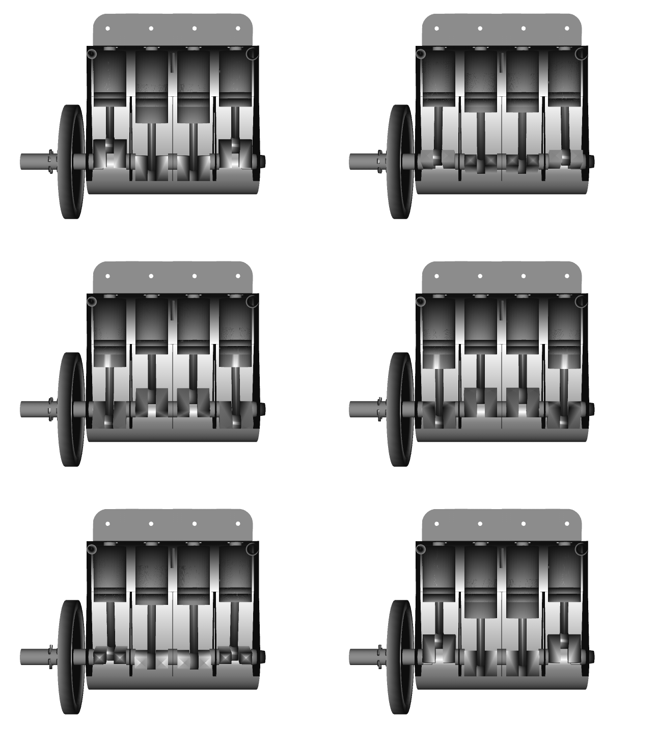
As viewed from the front, the curved section to the left holds the crankshaft which turns the propellers to produce thrust. The curved section is open so that you see can inside. In operation, a sheet steel plate was attached to the top to completely enclose the cylinder bays. There are four bays, separated by ribs, which hold the individual pistons and cylinders. The pistons are connected to the crankshaft by piston rods which move in the bays. The crankshaft turns on bearings which are located on the ribs of the crankcase.
This animation, viewed from the top of the engine, shows the installation of the crankshaft:

