Combustion Process
This is a computer drawing of one cylinder of the Wright brothers’ 1903 aircraft engine. This engine powered the first, heavier than air, self-propelled, maneuverable, piloted aircraft; the Wright 1903 Flyer. The engine consisted of four cylinders like the one shown above, with each piston connected to a common crankshaft which turns the propellers to produce thrust.
The brothers’ design is very simple by today’s standards, so it is a good engine for students to study to learn the fundamentals of engine operation. This type of internal combustion engine is called a four-stroke engine because there are four movements (strokes) of the piston before the entire engine firing sequence is repeated. In the figure, we have colored the fuel/air intake system red, the electrical system green, and the exhaust system blue. We also represent the fuel/air mixture and the exhaust gases by small colored balls to show how these gases move through the engine. Since we will be referring to the movement of various engine parts, here is a figure showing the names of the parts:
Mechanical Operation
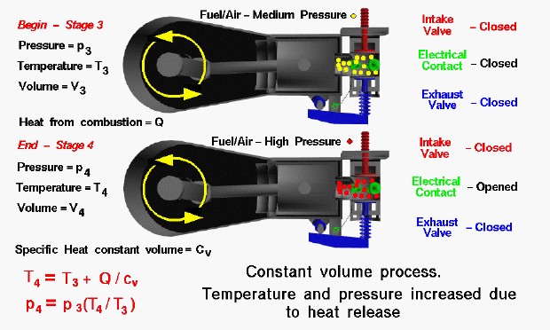
At the end of the compression stroke the fuel/air mixture has been compressed into the combustion chamber to a moderate pressure and temperature by the motion of the piston to the right. From our considerations of the engine cycle, we designate this condition as Stage 3 of the Otto cycle. The intake valve and exhaust valve are closed and the electrical contact is closed. The combustion process begins by opening the electrical contact through the action of the ignition cam and springs. As the contact moves away from the plug, a spark is produced which ignites the mixture. Igniting the fuel/air mixture results in rapid combustion of the fuel, a release of heat, and the production of exhaust gases. The combustion proceeds so quickly that we can consider the piston to be motionless and the volume of the combustion chamber to be a constant. The end of the combustion process is designated Stage 4 of the engine cycle and is the beginning of the power stroke.
Thermodynamics
Because the intake and exhaust valves are closed, the combustion of the fuel takes place in a nearly constant volume vessel. The combustion increases the temperature of the exhaust gases, any residual air in the combustion chamber, and the combustion chamber itself. From considerations of the first law of thermodynamics, the temperature increase is given by:
\(\LARGE T_4=T_3+\frac Q{cv}\)
where Q is the heat released and depends on the fuel and fuel/air ratio, and cv is the specific heat at constant volume, and T is the temperature. From the equation of state, we know that:
\(\LARGE p_4=p_3+\frac{T_4}{T_3}\)
where p is the pressure. The numbers indicate the two stages of the cycle. Since Q is a positive number, T4 is greater than T3 and p4 is greater than p3. Temperature and pressure in the combustion chamber both increase during the combustion process. The final value of the pressure depends on a temperature factor times the initial value of the pressure. The more that we can compress the gas (the higher the p3), the greater the final pressure, p4. The final work and power output of the engine depends on the value of p4. That is why we compress the gas as much as possible before combustion.