New Era In Aero
NASA Lewis Research Center utilized the SPL during the late 1960s and early 1970s for several niche research efforts while slowly introducing materials and testing equipment that would become prevalent in the ensuing decades.
Overview
In 1966, the NASA Lewis Research Center began reintroducing aeronautics into its research portfolio. The Apollo program was well on its way and the urgency of space research was ebbing. New aviation issues such as supersonic transport aircraft, noise and emissions reduction, energy efficiency, and vertical and short-takeoff flight had arisen in the interim. There were also efforts to modernize smaller general aviation aircraft. There was also renewed interest in new materials and coating systems for turbines.
Lewis utilized the Special Projects Laboratory (SPL) during the late 1960s and early 1970s for several niche research efforts while slowly introducing materials and testing equipment that would become prevalent in the ensuing decades.
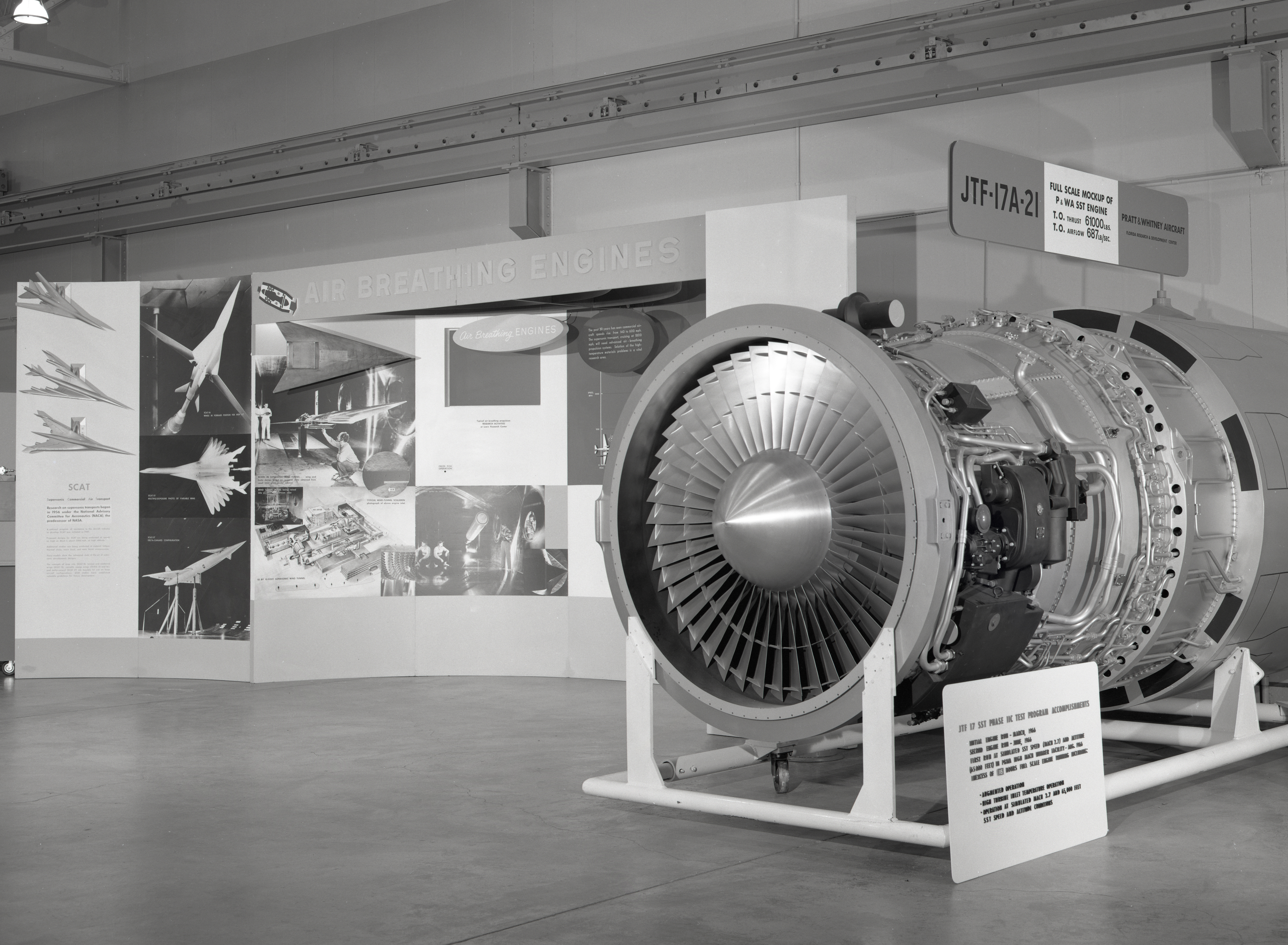
Supersonic Transport Support
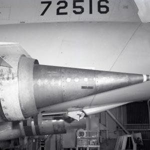
The United States initiated the national Supersonic Transport (SST) program in 1963 in an effort to develop high-speed airliners. Boeing was tasked with designing the aircraft and General Electric the engines. Lewis, which served as a technical consultant, undertook a large-scale research program in the late 1960s to improve engine supersonic inlet and nozzle designs. The noise levels generated by the SST were a major concern, so great care was taken to develop the exhaust nozzles. In the late 1960s, Lewis tested three nozzle concepts (two created by General Electric and a Lewis-designed plug nozzle) on General Electric J-85 engines in its wind tunnels, altitude chambers and finally on its F-106B research aircraft. The plug nozzle showed the most promise.
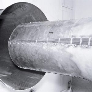
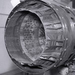
It was necessary to lower the temperatures of these nozzles, so Lewis conducted an experimental cooling program in late 1960s and early 1970s. At the time, there was not a proven system for predicting cooling performance for uninsulated engine components. In the late 1960s, Lewis established a program to develop accurate methods of predicting the efficiency of different film and air cooling systems for aircraft engine components. Lewis researchers had created cooling correlations for rocket engine nozzles, which were very different in shape than aircraft tailpipes. Lewis began the investigation by comparing data from three predictive equations to the performance of a film-cooling system installed on a J-85-13 engine with a cylindrical ejector nozzle. Film cooling refers to the process of using an ejector to generate a buffer of cool air between the hot exhaust gas and the uninsulated tailpipe shell.
In 1966, the researchers operated the J85-13 in Cell 2 of the Jet Propulsion Static Laboratory (JPSL) with an afterburner and cylindrical diffuser shell. They compared the performance data to that generated by the three predictive calculations. They initially found that the predicted cooling data did not match the actual engine cooling, but the application of a mathematical correction for radiation and free-convection effects on wall temperatures improved the findings. The correlation was updated and the tests were repeated over a larger range of conditions in an altitude chamber. The researchers concluded that one of the correlations was fairly effective for predicting ejector wall temperatures with film cooling but tended to predict lower than actual temperatures for the plug nozzle.
Congress cancelled the national SST program in 1971 due to a combination of design issues, economic concerns and environmental fears. Lewis continued to support its successor, the Supersonic Cruise Aircraft Research (SCAR) program, which included nozzle research, into the 1980s.
Documents
- J85-13 Heat Transfer Characteristics for a Cylindrical Ejector (1968)
- Exhaust Nozzles for Propulsion Systems on Supersonic Cruise Aircraft (1990)
Images
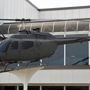
Helicopter Heat Redirection
The performance of helicopters improved substantially after World War II with the incorporation of turboshaft engines. Turboshafts are gas turbines that use their energy to rotate shafts rather than create thrust. Helicopter use increased during the Korean War, but they became critical to the overall mission in the Vietnam War, including their first application as a weapon. In the early 1970s, Lewis and the U.S. Army cooperated on several helicopter programs involving transmissions and noise reduction.
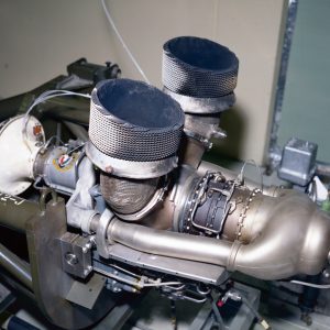
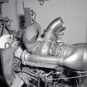
The military discovered during Vietnam that low-altitude reconnaissance helicopters, such as Hughes Aircraft’s Kiowa OH-58, were susceptible to infrared heating seeking missiles. Hughes engineers sought to combat the issue by replacing the T-63 engine’s twin exhaust stacks with ejectors. The ejectors consisted of an insulated duct surrounded by an external shroud that included cooling fins to lower the exhaust temperature. In addition, the new design directed the exhaust vertically instead of horizontally.
Lewis was asked to determine if the new ejectors would hinder the OH-58’s performance. In 1976, engineers installed an Army mobile engine test stand in Cell 2 of the SPL to test the T-63 and mounted a hood over the vertical ejectors to remove the exhaust from the test cell. They operated the engine at various power levels with and without the ejectors. The runs demonstrated that new ejectors did not affect engine performance. Hughes integrated the modified stacks into the new OH-58C models in the late 1970s. The Army utilized the Kiowa OH-58 extensively during the wars in Iraq and Afghanistan before phasing them out in 2017.
Documents
Images
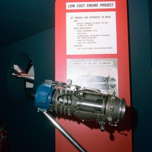
Low Cost Engine
One area of aviation that did not advance during the 1960s was general aviation. General aviation is a broad term that refers to all non-airline civilian aviation, including both business and personal flights. The general aviation market boomed in the 1920s and 1930s, but a post-war slump emerged due to rising prices and a lack of technical progress. By the 1960s, jet engines powered most military and commercial aircraft, but they were too expensive to be practically incorporated into smaller civilian aircraft. Engines have traditionally been the most expensive component of smaller aircraft. In the late 1960s, Lewis undertook a multiyear effort to reduce the cost of small turbojets for general aviation. The Navy decided to co-sponsor the effort, referred to as the Low Cost Engine, in hopes of utilizing the inexpensive engines for its drone aircraft.
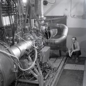
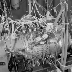
Researchers closely analyzed ways to simplify each engine component without incurring performance penalties. One of the more complicated and expensive components was the fuel control system. It had to properly meter the fuel during all phases of flight without surging or stalling the engine. Lewis researchers developed a new fuel system that offered potential reductions in expense and complication by utilizing linear functions. In 1969, they tested the system on a General Electric J85-13 engine in Cell 1 of the SPL. The tests demonstrated that the linear fuel system provided satisfactory engine performance with smooth and prompt acceleration.
Meanwhile, Lewis staff designed a four-stage, axial-flow Low Cost Engine. NASA contracted with a manufacturer to fabricate four of the 11.5-in.-diameter and 100-lb sheet metal engines for testing at Lewis. The four engines were first tested in 1971 at sea level conditions in Cell 1 of the SPL. Although poor compressor performance prevented the engine from achieving its full 600-lb thrust capability, the researchers were able to obtain 700 lb of thrust by operating the engine slightly above its design speed. After a redesign of the compressor, the engines were tested during 1973 in simulated flight conditions in an altitude chamber. Additional runs with the new design were also performed at the SPL.
The program was considered a success. Fabrication of the NASA Low Cost Engine was estimated to cost $3,000, and the Navy flight tested the engines in its drone aircraft. NASA released the design to private industry so that design elements would be incorporated in future projects and reduce the overall cost of small jet aircraft. Small jet and turboprop engines had become relatively common in general aviation aircraft by the late 1970s.
Documents
- J85-13 Experimental Fuel Control Test (1973)
- Low-Cost Expendable Turbojet Engine–Design and Fabrication (1976)
- Low-Cost Expendable Turbojet Engine–Performance (1976)
- Cost Reduction on Turbine Engines for General Aviation (1971)
- Experience with Low Cost Engines (1973)
Images
Wind Turbine Blades
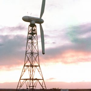
NASA began downsizing as the Apollo Program reached its conclusion in the early 1970s. As such, Lewis began exploring new areas of research with terrestrial applications, such as energy conversion and alternative sources of power. NASA partnered with the Department of Energy to develop a series of experimental large horizontal axis wind turbines that would tie into the power grid. The efficacy of the blades was one of the critical design aspects. Engineers found that riveted aluminum blades from their initial design deteriorated quickly and were difficult to repair. Lewis researchers then worked with a contractor on a redesign that employed sheets of laminated wood joined with an epoxy and attached to the rotor with metal studs. Before testing the wooden composite blades on NASA’s wind turbines, Lewis engineers wanted to analyze and perfect the bonding and joint design. The juncture of the blade and the rotor shaft was an area of high stress loads.
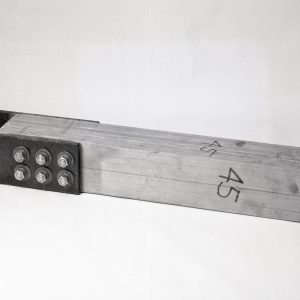
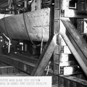
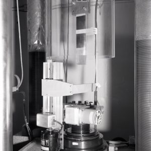
A contractor created the 4- by 4- by 24-in. laminated fir or ash plywood-type sections, each using a slightly different thickness of ply. A hole was drilled in one end where the steel bolt was inserted with epoxy. Lewis’s wood shop then attached two steel plates to other end with bolts and epoxy. Researchers then installed these sections in a 100,000-lbf multiaxial tension machine in Room 104 of the SPL. The researchers investigated the effect of different types of wood, geometries, epoxies, bolts and holes. Over the course of dozens of runs, each block was pushed to its failure point.
Once the optimal configuration was identified, NASA had four sets of full-scale wooden blades manufactured and installed on its 200-kW wind turbines located around the country. The endurance tests conducted between 1980 and 1982 demonstrated that despite some small cracks, the wooden blades were structurally sound, applicable to large machines and easy to repair. Lewis also successfully tested fiberglass blades. Both wood and fiberglass designs have since been employed in commercial wind turbines.
Documents
- Evaluation of Laminated Wood Wind Turbine Blade (1981)
- Wind Turbine Wood-Epoxy Blade Test (1978)
- Evaluation of Laminated Wood Blades on the Mod-OA Wind Turbine (1983)
- Properties of Laminated Douglas Fir/Epoxy Composite (1990)
Images