Turbine Cooling
The Jet Propulsion Static Laboratory (JPSL) transitioned to turbine work as turbine cooling became a priority in the late 1940s and 1950s.
Overview
By the late 1940s, the jet engine had established itself as the future of aircraft propulsion. Spurred by the military, engine manufacturers sought to continually improve engine performance and efficiency while reducing costs. The growth of the jet engine’s capacity rose exponentially in the early 1950s. The National Advisory Committee for Aeronautics (NACA) laboratory in Cleveland, Ohio, renamed the Lewis Flight Propulsion Laboratory, reorganized its staff in 1949 and added new facilities to address more powerful engines. In addition, three spin pits were installed in the Jet Propulsion Static Laboratory (JPSL) shop area.
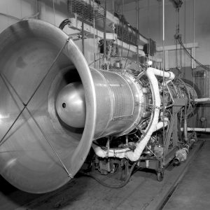
One area of concern was the turbine. The turbine is a fan fixed to the drive shaft downstream from the compressor and combustion chamber. The hot exhaust flows through the turbine on its way out of the tailpipe. This spins the turbine, which in turn rotates the drive shaft, which spins the compressor to keep the engine running. The intricate turbine blades not only have to endure the stress of high-speed rotation but also the extreme heat flowing from the combustion chamber. NACA researchers sought to improve turbine performance by refining their shape, analyzing temperature resistant materials and thermal coatings, and developing cooling systems. Lewis made turbine research a priority in the late 1940s and 1950s.
Documents
- Turbine Research Inspection Talk (1947)
- Turbine Research Inspection Talk (1949)
- Turbine Cooling Limitations and Future (1970)
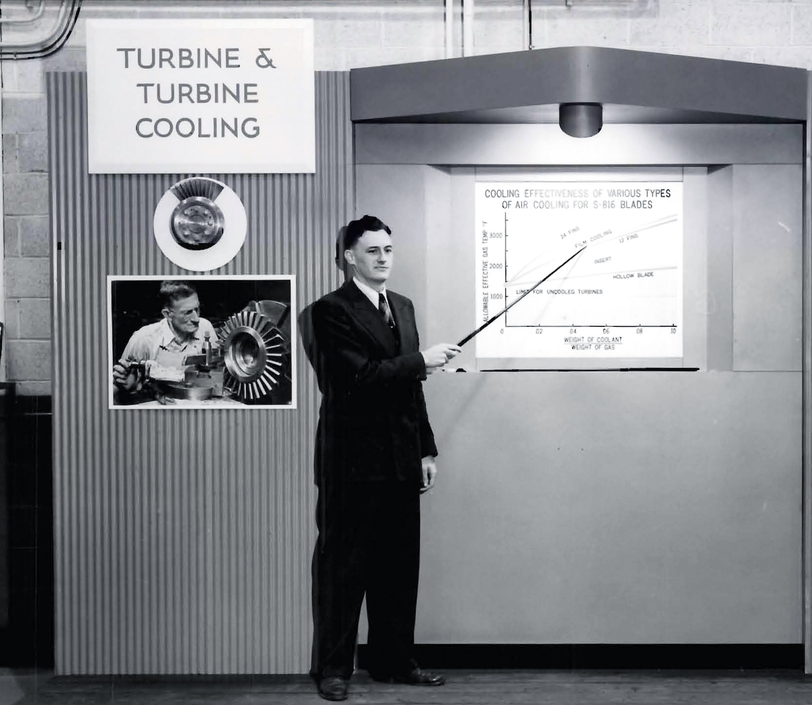
Air Cooling
The amount of thrust an engine produces is limited by the amount of heat that the turbine can withstand. One method of increasing this capability is by cooling the hot surfaces. The goal is to provide the maximum amount of cooling using a minimum amount of coolant. Lewis investigated three types of convective cooling of turbine blades: removal of heat at the blade root, air flow through hollow blades and liquid coolant flow through hollow blades. The lab was also studying different heat resistant materials, but cooling was a more cost-effective tactic. Air cooling, which diverts excess air flow from the compressor into hollow turbine blades to carry away the heat, is the least expensive type of cooling.
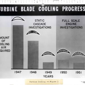
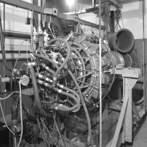
In 1945, Lewis researchers began studying the flow of air through hollow turbine blades. They determined that the efficiency of this system improved when fins were placed in the passages. They also experimented with modified leading or trailing edges. During 1948 and 1949, Lewis developed a method of fabricating these finned blades and established methods for predicting engine performance relative to turbine cooling. Much of this initial research was performed on test rigs with just the turbine. By 1950, these experimental turbines were tested on full-scale engines, including the General Electric I-40 in Cells 3 and 4 of the JPSL.
An analytical study predicted that applying cooling to engines operating at contemporary temperatures would likely result in better performance than cooling higher temperature engines. The goal was to reduce the amount of critical and costly materials needed. In 1953, researchers tested this theory on a Westinghouse TG-190 in Cell 6 of the JPSL. A compressor supplied cooling air to the iron turbine blades, which included corrugated inserts, to increase heat transfer. At a constant speed, the thrust increased proportionally to the level of cooling air. The findings verified the theoretical predictions.
As engines increase speed, the inlet air temperature rises, which diminishes the effectiveness of air cooling. Nonetheless, internal convective air cooling was the primary engine cooling method in the 1960s and 1970s. Since the 1970s, it has been used in conjunction with external film cooling and impingement. Film cooling ejects cooling air from holes in the blade, resulting in a thin layer of cool air on the blade surface. Impingement systems shoot cooling air against the inside of the blade walls to facilitate the heat transfer. Cooling has allowed engines to operate at temperatures above the temperature limits of their materials, thus producing more thrust.
Documents
- Investigation of Cooling Air on Two Jet Engines (1956)
- Performance of Axial-Flow Engine with Air-Cooled Turbine (1955)
- Air-Cooled Turbine in Turbojet at Temps up to 2,500 °F (1961)
Liquid Cooling
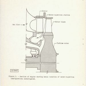
Liquid-cooling systems provide the best method of moderating turbine blade temperatures, but they require additional components and add weight to the engine. There are different liquid-cooling approaches, including film cooling and blades with cooling passages. The earliest method of cooling with liquids, however, involved spraying water into the airflow ahead of the turbine. The water strikes the hot blades and evaporates, carrying away the heat as it exits the tailpipe. Early spray-cooling systems were tested on jet engines in Great Britain. Although the cooling proved to be uneven, it was sufficient to warrant further research.
Spray cooling requires large quantities of water. Therefore, it would not be practical for normal flight, but NACA engineers hoped it could be used to reduce turbine temperatures during takeoff and afterburning situations. Researchers installed a spray system in a General Electric I-40 engine and tested it in the Torque Stand in 1950 and 1951. The water cooled the blades, but resulting temperature variations caused some of the blades to fail. The system was modified and retested at the JPSL during the summer of 1952. The I-40’s thrust increased, but thermal shock and inadequate cooling of the blade tips and edges resulted in blade failures. Further tests using blades cast from different alloys produced similar results. Spray cooling was thus shelved.
The NACA liquid-cooled turbine experiments, and those by manufacturers such as General Electric, were designed without grasping the complexities of engine heat distribution. NASA and industry continue to explore the concept as newer, more powerful engines emerge, but to date, there is no liquid cooling for turbine technology that has been proven flight-worthy. This is due to the complexities, poor heat transfer and lack of coolant flow data in liquid-cooled systems.
Documents
- I-40 Engine Performance Using External Water-Spray Cooling (1954)
- Status of Liquid-Cooling Technology for Gas Turbines (1979)
Turbine Materials
In addition to cooling, NACA researchers were also studying new turbine blade materials that could perform under high temperatures. The extreme heat causes atoms to vibrate and move, which reduces the durability of a material. The escaping atoms can also cause corrosion as they react with other elements. Although the alloys traditionally used for turbines are reinforced with hard particles, they can lose strength at higher temperatures. Cermets, also known as ceramels, are composite materials that include both metals and ceramics. They are lighter than alloys, can withstand higher temperatures and do not require large quantities of strategic materials. The disadvantages include difficulty in affixing them to the turbine wheel and sensitivity to impact damage, particularly damage from a broken blade.
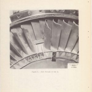
Lewis conducted an intensive study of cermet turbine blades in the mid-1950s that included fundamental sintering studies, the development of fabrication techniques and engine testing of the blades in the JPSL and other test stands. Titanium carbide-cobalt cermets were of particular interest. Early spin testing of these blades revealed that failures occurred most frequently at the base of the blade. Researchers studied different methods of fastening the blades to the wheel.
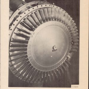
They used the JPSL to test different shaped titanium carbide-cobalt based cermet blades with four different root configurations on a General Electric I-40 engine. They retested the two most promising designs with the engine operating at higher speeds, but the blades quickly failed. The researchers were able to improve the durability by offsetting and skewing the blade root. Follow-up testing validated the modifications to the root and indicated that the cermet was stable enough for use in full-scale engines.
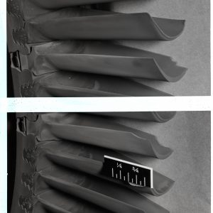
The researchers continued the study by replacing the rectangular root shape with a curved root, which simplified the design and reduced the loads. The new root design was incorporated into an I-40 engine and tested for 150 hours in the JPSL. Unlike the previous tests, they concentrated on the reliability of the blades for service life rather than trying to determine their maximum life. The curved root design proved to be superior to the rectangular base, so the researchers decided to use a General Electric TG-190 to test it an axial-flow compressor engine. The turbine wheels in axial-flow engines exert less stress on the blade than centrifugal engines such as the I-40. The TG-190 was run 16 times in the JPSL with varied blade installations and geometries. The tests produced only one root failure, but there was widespread chipping of the other portions of the blades. This led the researchers to conclude that cermets were not applicable to axial flow engines.
The center continues to conduct research on cermets and other composite materials. General Electric has introduced composite fan blades into its engines in recent years. Composites have yet to be used for turbine blades, however.
Documents
- Investigation of Root Designs for Cermet Turbine Blades: Root Design Alterations (1953)
- Investigation of Root Designs for Cermet Turbine Blades: Curved-Root Design (1955)
- Investigation of Cermet Turbine Blades in an Axial-Flow Engine (1957)