Facility Description

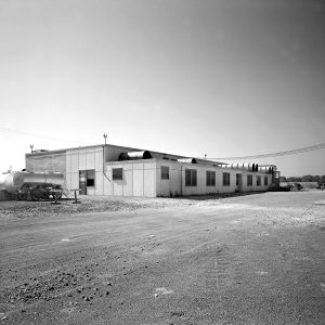
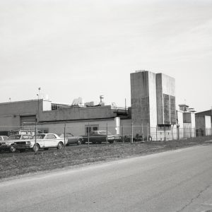
The Jet Propulsion Static Laboratory (JPSL), was a rectangular single-story structure located near the southern edge of the NASA Glenn Research Center. It contained six test cells, three control rooms, several shops and additional test areas.
Overview
The SPL initially contained only two test cells and a control room. Two additional cells and another control room were built by 1945. Over the next several years, two larger cells, three spin pits and another shop area were added. The test cells were designed to operate jet engines at sea level conditions. They were reconfigured over the years as research needs evolved, and the name of the facility was changed to the Special Projects Laboratory (SPL). Beginning in the 1970s, equipment for materials testing was installed in several of the test cells and shop areas.
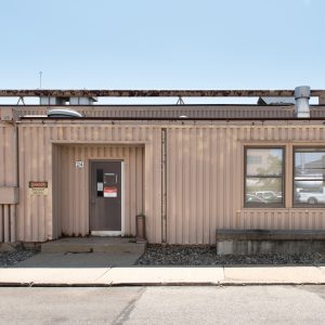
There were minor modifications to the building’s exterior and utility systems in the 1980s, but the general layout remained the same as in the mid-1940s. Although the SPL test cells remained active into the 2000s, maintenance and upkeep of the facility waned. In 2012, NASA decided to remove the building as part an agency effort to decrease its physical footprint. Glenn relocated the test rigs to other facilities before demolishing the SPL in 2018.
Documents
Images
Building
The SPL evolved during its initial years, but the original portion (referred to below as Section A) was a roughly 65 footsquare wood structure built around two reinforced-concrete engine test cells with a control room between them. The concrete block walls sat on an underground concrete spread footing. The roof structure was supported by 2-by-14-inch wood joists. The addition of four test cells and several new shop areas in the mid-1940s extended the building’s length to 226 feet. The area containing Cells 5 and 6 (Section B) at the southern end of the building was physically different than the rest of the building. Henceforth, the basic shape of the SPL remained unchanged throughout its lifetime.
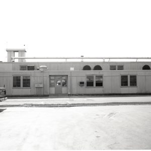
The 143 feet long and 65 feet deep Section A housed Cells 1 through 4, two control rooms, two smaller test cells, three shop rooms and a restroom. The shop and access-way areas were 10 feet high, while the test cell areas were 14 feet high. Section A had six sets of windows with a doorway in the center along the front wall and a doorway and two windows on the northern wall. The rear of this area included four doorways, a series of concrete pads and portals in each of the test cells for exhaust lines.
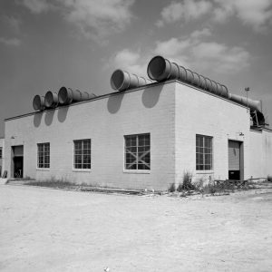
The 80-by-83-foot Section B contained Cells 5 and 6, a control room, the compressor and two shop areas. The shop and access-way areas were 23 feet high and the test cell area was 17 feet high. The front wall contained a truck door and three sets of block windows. The southern wall included another truck door and two pedestrian entrances. The exterior of the western wall behind the test cells was dominated by two 22-by-34-foot vertical concrete mufflers and had doorways off of the control room and compressor area.
Documents
Images
Test Cells
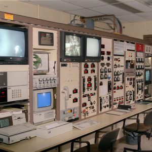
The facility’s first two 10-by-20-foot test cells were nearly identical and shared a control room. Double steel doorways provided access to the main corridor. Cells 1 and 2 included 127-by-55-inch bedplates that could support engines producing 5,000 to 10,000 pounds of thrust. Cell 1 had a concrete slab behind it on which engine researchers could test engines. Cell 2 had a large J-shaped concrete acoustical housing behind it to reduce the engine noise levels. The control room, located between the two cells, housed the equipment to remotely operate the engine and record data. The room included small reinforced windows that allowed the researchers to view the engines in the adjacent cells during the tests.
Cells 3 and 4 were identical to the original two cells in layout and size but could operate slightly larger engines. Cell 3 had a 132-by-57-inch bedplate that handled engines with up to 6,000 pounds of thrust. There was also a concrete slab behind it on which engines were occasionally tested. Cell 4 had a 228-by-55-inch bedplate for testing engines producing 8,000 pounds of thrust, and like Cell 2, had a large vertical concrete acoustical housing in the rear. The shared control room between Cells 3 and 4 was similar to the room for Cells 1 and 2.
Rooms 112 and 111 were located between Cells 2 and 3. This area originally contained the boiler and an instrumentation room, but by the mid-1940s, the space was divided into two cells for auxiliary testing—each with a rear room attached. There was a window in the wall between Rooms 112 and 111. The rear room portion of Room 112 included a 4-by-4-foot pit that formerly stored a boiler pump. A roughly 10-by-30-foot concrete extension was added behind these two rooms in the 1950s.
Cells 5 and 6, located in Section B at the southern end of the facility, were larger and more powerful than the others. The thrust plates were 21 feet by 8 feet, 3 inches and could handle engines producing 9,000 to 10,000 pounds of thrust. Cell 5 was 22 by 41 feet in size and had a 21-foot-by-8-foot-3-inch bedplate that could accommodate engines producing up to 10,000 pounds of thrust. Cell 6 was 17 by 41 feet with an identical bedplate to handle engines producing up to 9,000 pounds of thrust. Each cell had a large concrete exhaust stack behind it that was roughly 34 by 8 feet in area. The control room between the cells was 15 by 46 feet in size.
Images
Test Equipment
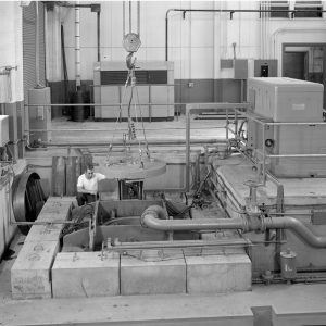
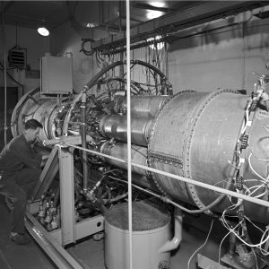
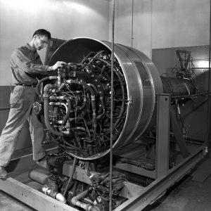
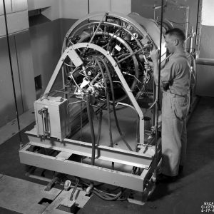
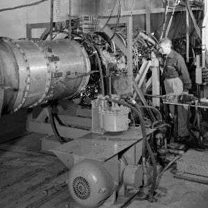
For engine testing, mechanics mounted the engine being tested on a steel frame suspended from the ceiling. The engine’s tailpipe extended through a portal in the rear of the cell to discharge its exhaust. The engine was supplied with fuel through flexible hoses. A 53-inch diameter air line introduced atmospheric air from the front of the building into the upper portion of the test cell. The flow passed through a nozzle that expanded from 18 to 26 inches to equalize the pressure of the incoming air flow with the test cell pressure. A series of thermocouples and rakes attached to the engine measured temperatures and pressures. A crank lever and pressure cell on the frame measured balancing pressure as means of estimating thrust.
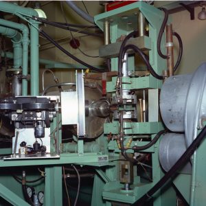
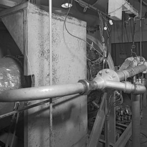
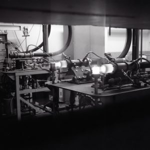
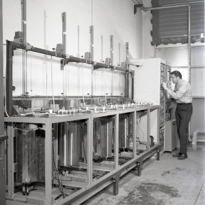
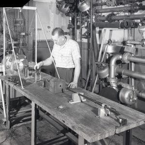
Much of the SPL’s materials testing used different variations of high-speed burner rigs. The original devices were small devices that combusted jet fuel or natural gas to create a concentrated 3,000 °F high-speed air stream. A cylindrical stand rotated the test specimens in and out of the hot gas stream. Maintenance and repairs are minimized because the rig itself does not have to be cycled; the samples are merely removed
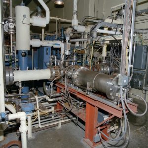
The High Pressure Burner Rig (HPBR) had a 400-hp compressor to supply to the combustor where it is ignited. It flowed through cooled transition sections and the 6-inch diameter T-shaped test section. A water spray nozzle cooled the gases after they pass through the test section, and then they passed through a scrubber before being discharged into the atmosphere.
The Replaceable Blade Turbine (RBT) combusted a jet fuel and salt mixture. The pressurized hot flow could be directed to a test stand with three articles or a single-stage turbine with 28 blades. The facility could automatically operate for 100 hours.
It is a high-speed pressurized burner rig that simulates conditions inside an engine. It can generate temperatures of 1,832 °F and 4 atmospheresof pressure. A salt mixture is injected into the airstream immediately after combustion with jet fuel. The stream passes through a nozzle and enters the pressurized and temperature adjusted test section then spray-cooled with water. The test section can accommodate two samples simultaneously.
In the Hot Corrosion Test Facility (HCTF), a salt mixture was injected into the airstream immediately after combustion with jet fuel. The stream passed through a nozzle and enterd the pressurized and temperature adjusted test section then spray-cooled with water. The test section could accommodate two samples simultaneously.
Infrastructure
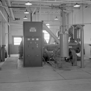
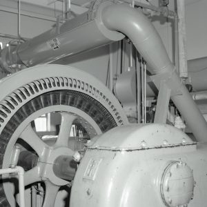
A 500-hp Ingersoll Rand compressor was located in Room 103 of Section B. The two-stage reciprocating compressor supplied the test cells with 125 psi at 180 pounds per minute auxiliary air pressure. The compressor complemented three identical machines in the other building to provide clean, dry compressed air to several facilities.
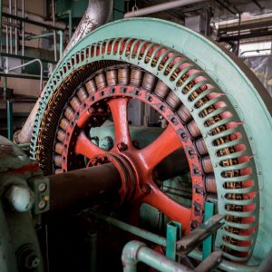
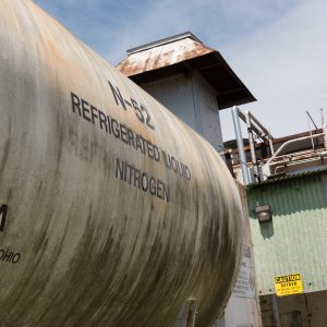
The SPL included three induction heating units of 75, 15 and 30 kW of power. Two motor-generator sets powered the instruments, a test rig in Room 112 and the air compressor. A portable 300-kW electro-starter was used to start the engines in the test cells or pits. There were nine fuel tanks, including two 12,000 gallon jet fuel tanks and a 5,000 gallon special fuels tank. The SPL’s basic utilities such as steam, electricity, water and air were tied to the larger lab sources.
Images
Shops and Offices
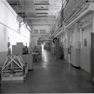
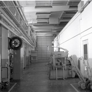
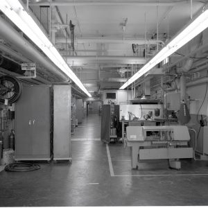
A 78-by-19-foot hallway ran the length of the building, separating the test cells and control rooms from the shops and offices. There was a pedestrian entrance at the north end and a truck door at the south end. Doorways from both the test cells and shop areas opened into the central hallway. A 3-ton monorail crane ran the length of this accessway. A double doorway separated the Section A portion of the hall from the Section B segment. In the mid-1960s, the rectangular Room 100A was built in the central portion of the hall. In the early 1990s, a small room (Room 116A) was added to the hallway near the north end of the building.
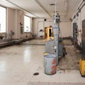
Section A contained a series of four 19-foot-wide rooms along the front of the building. In the center of these was a small foyer for the front entrance. There was a restroom in the northern corner. Section B originally had one large shop area with two spin pits below grade in the center that was open to the main hallway. In the mid-1960s, the shop was given a ceiling and enclosed with cinderblock walls, which separated it from the hall. The spin pits were floored over at this time. A 10-ton double bridge crane spanned both the hallway and the shop. The shop rooms were fairly nondescript. Most had tiles over concrete flooring and sheetrock walls with transite panels attached.
Images