Pumps and Tanks
In the late 1950s and early 1960s, the Lewis Research Center’s work with liquid hydrogen began shifting from combustion and cooling to the handling of the cryogenic fluid. High-performance liquid-fueled rockets require turbopumps to pump the fuel and oxidizer from their tanks to the fuel injectors at high rates of speed. These devices must operate at hundreds of rotations per minute and be able to restart themselves numerous times during a mission. Hydrogen pumps pose particular challenges since the cryogenic fluid is often near its boiling point. Cryogenic propellant tanks for space applications must be lightweight but sturdy enough to contain a heavy gas such as helium to naturally push the liquid into the supply line. Tanks also require insulation to prevent the cryogenic fuel from evaporating.
These issues had applications for the Centaur, Saturn, and nuclear rocket programs, as well as future long-duration missions to other planets. The Rocket Systems Area made important contributions to the mastering of the pumping and storage of liquid hydrogen.
Documents
- NASA Axial-Flow Turbopumps (SP 1978)
- NASA Centrifugal Turbopump SP (1973)
- Liquid Rocket Turbopump Inducers SP (1971)
- Liquid Rocket Metal Tanks and Components SP (1974)
Boiling Hydrogen
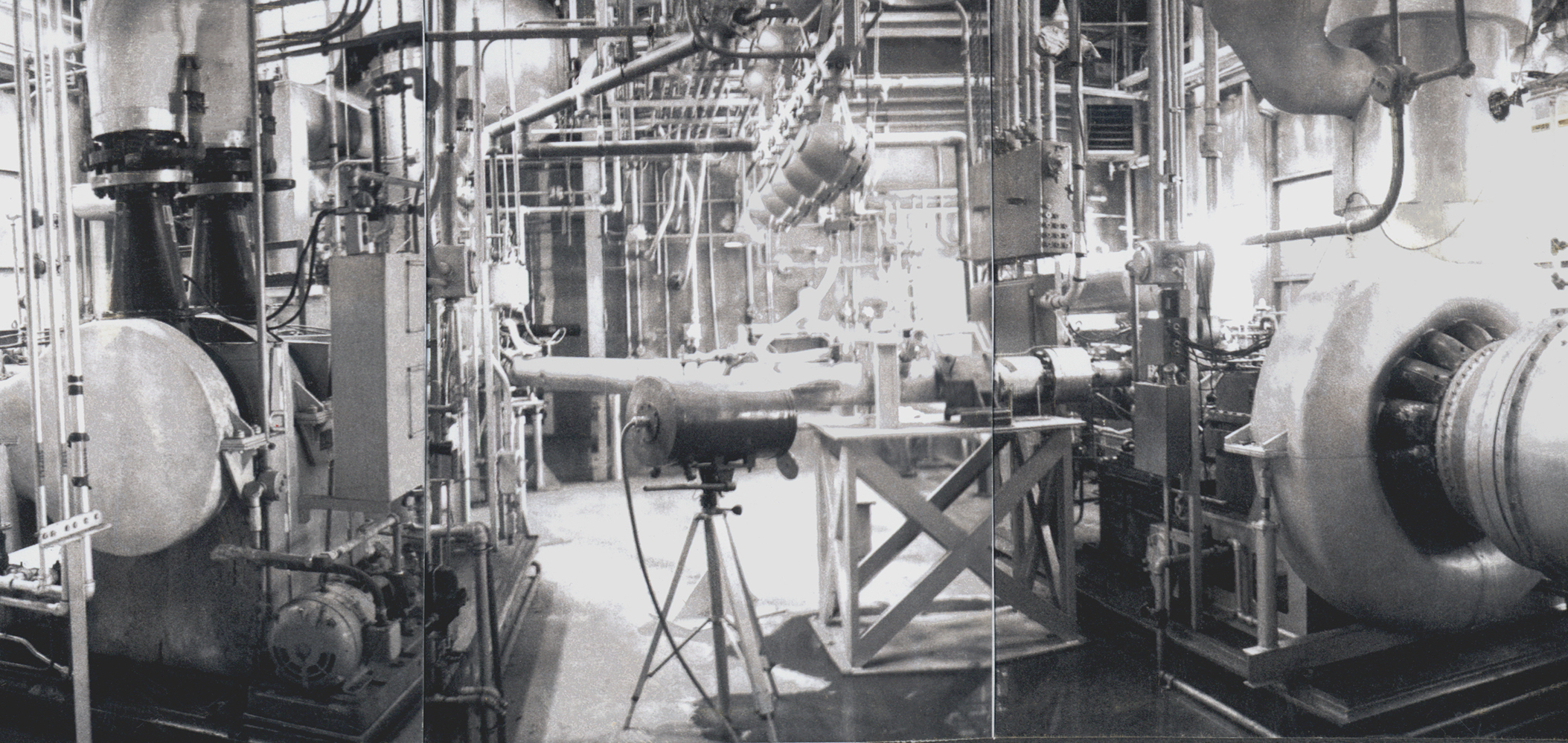
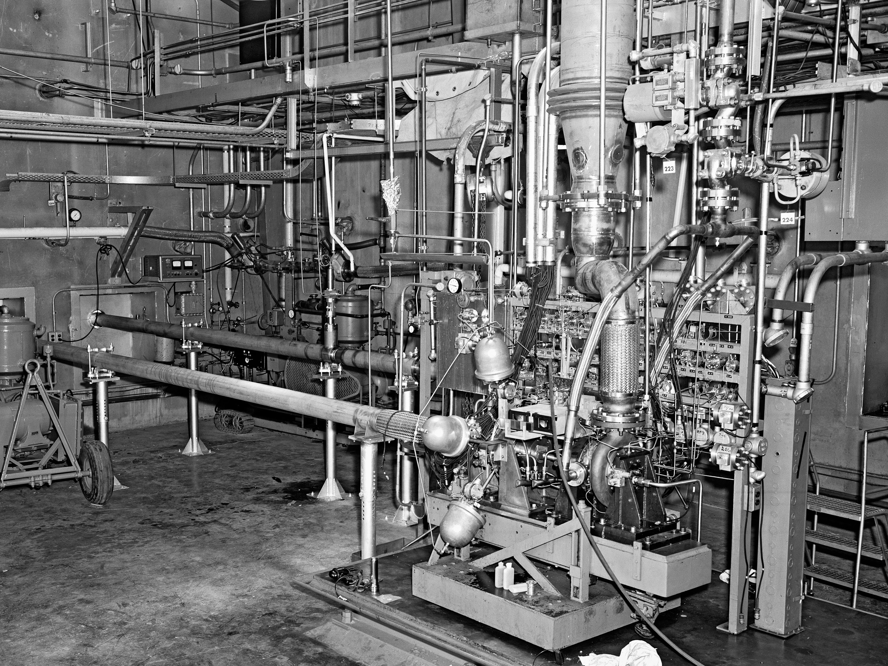
Hydrogen is usually stored just under its –423 °F boiling point so it is often evaporating, forming bubbles, as it enters the pump. Researchers strove to reduce thiscavitation, which impairs the performance of the turbopump and eventually cause its physical degradation. Engineers designedimpellersand inducers (spiral-shaped rotors that increased flow) at the pump’s inlet to reduce the effects of cavitation.
Researchers used the hydrogen test loop at the Liquid Hydrogen Pump Facility (A Site) to study different impeller and inducer designs on centrifugal and axial-flow turbopumps. They were particularly interested in the coordination of different inducer and impeller designs to optimize flow and limit the effects of cavitation. Each test was run over three speeds while the liquid-hydrogen flow decreased from a maximum level to the point where the pump stopped. The researchers found that inducers with a flow rate that was higher than that of the impeller reduced cavitation but did little to stabilize the propellant flow. They also used A Site to compare the performance of impellers with and without shrouds, which were designed to prevent recirculation of the fluid.
Documents
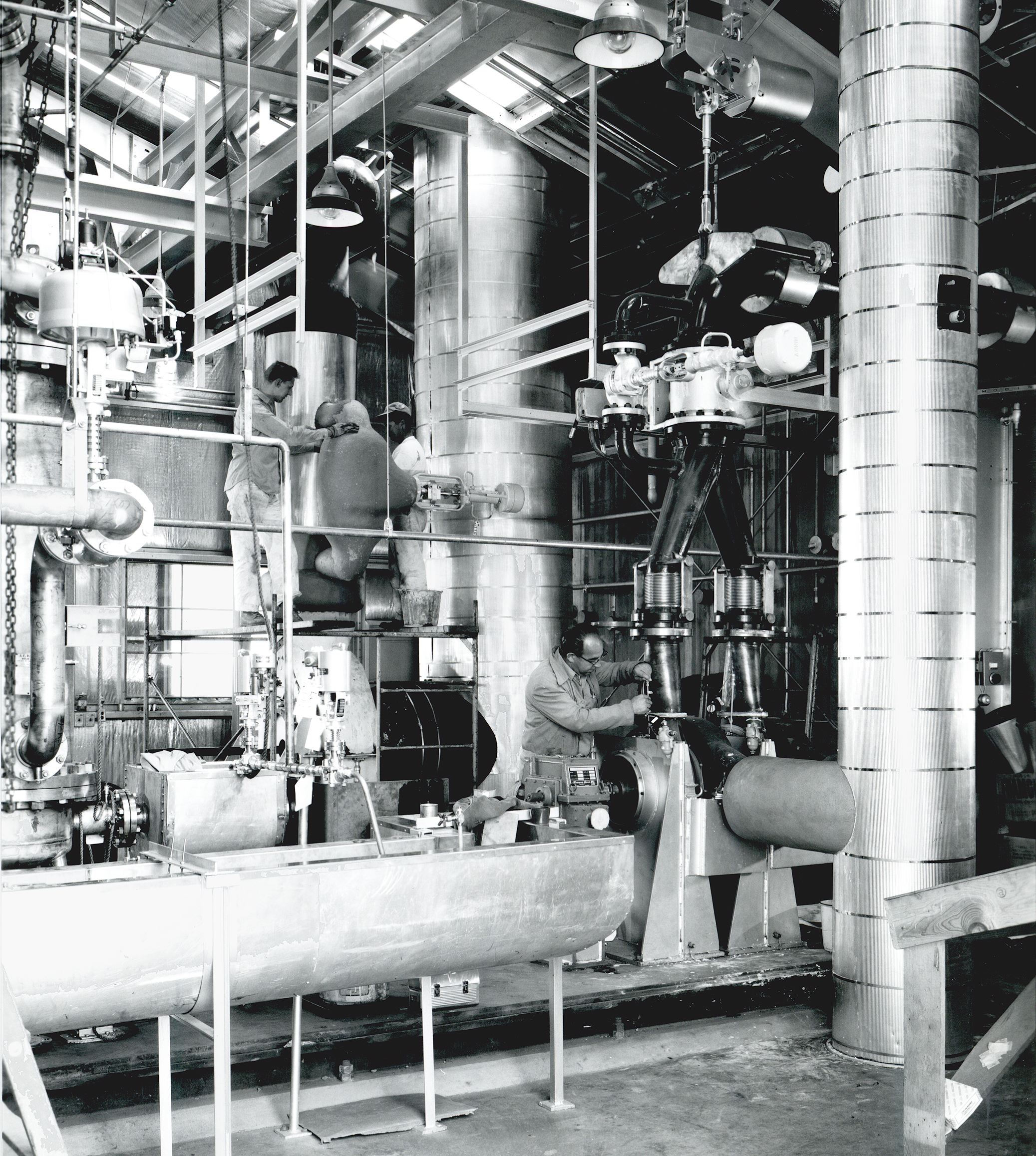

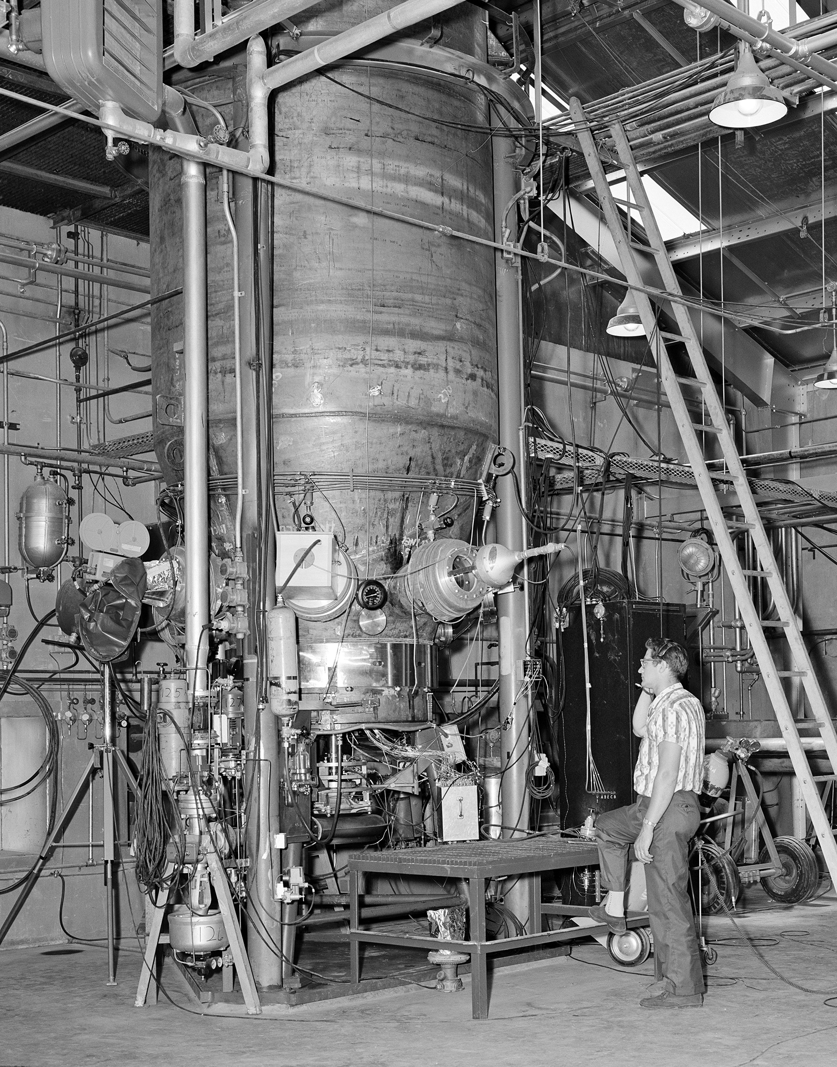
NASA designed the Boiling Fluids Rig at the Turbopump Facilty (C Site) specifically to study pumps operating in cavitating conditions. The experimental turbopump was submerged in a large tank of boiling hydrogen. Lewis researchers conducted extensive studies into the relationship between inducer and pump performance. They analyzed the inducer blade thickness and angles, the length of the propellant supply line, and the effect of radiation heating on the fluid. They also investigated the pumping of colder slush hydrogen, which could reduce the size of the fuel tanks.
Documents
- Performance of Line-Mounted 80° Inducer in Hydrogen (1967)
- Performance of Helical Inducer Operated in Hydrogen(1967)
- Change in Pressure Requirement in Low Temperature Hydrogen(1968)
- Effect of Leading Edge Thickness on Inducer Performance (1970)
- Performance of 78° Helical Inducer in Hydrogen(1976)

Fluorine Pumps
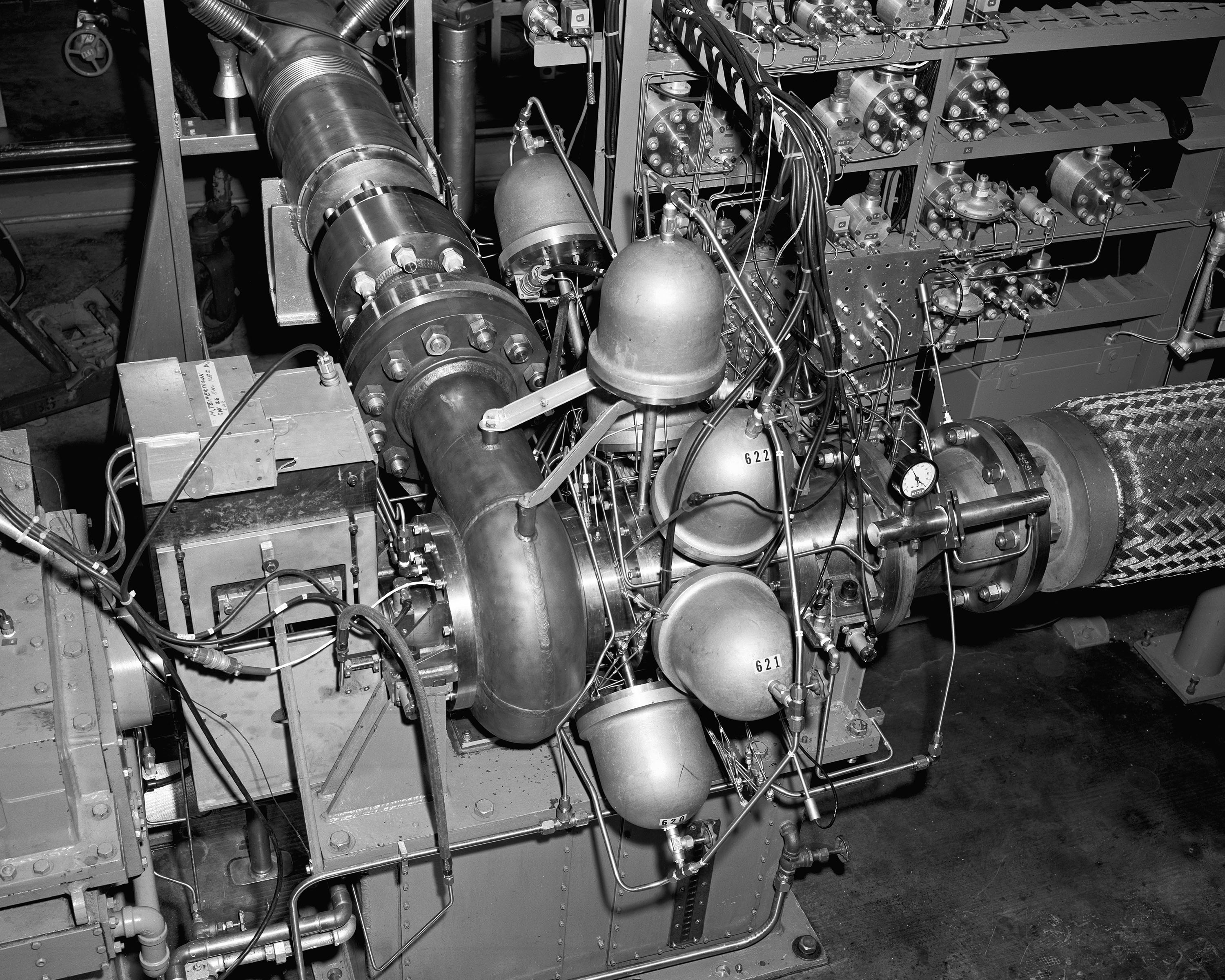
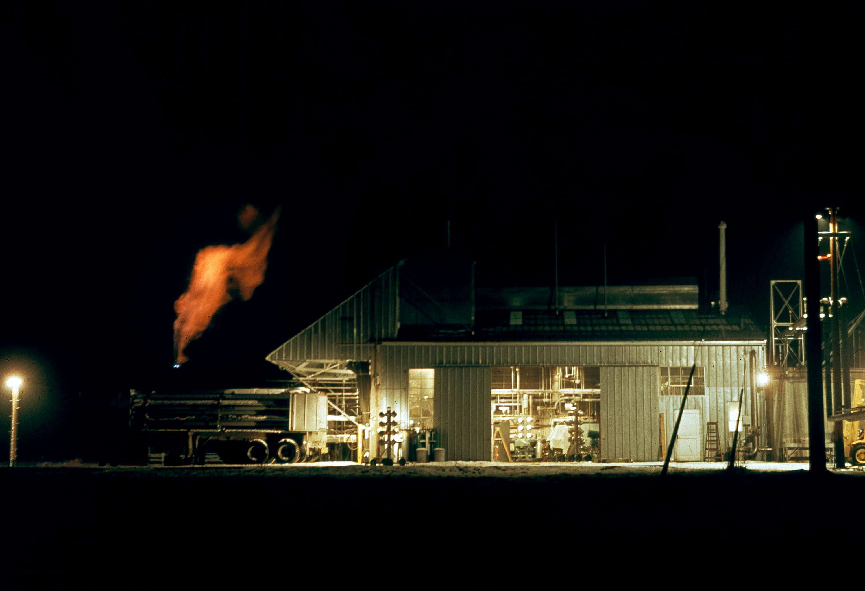
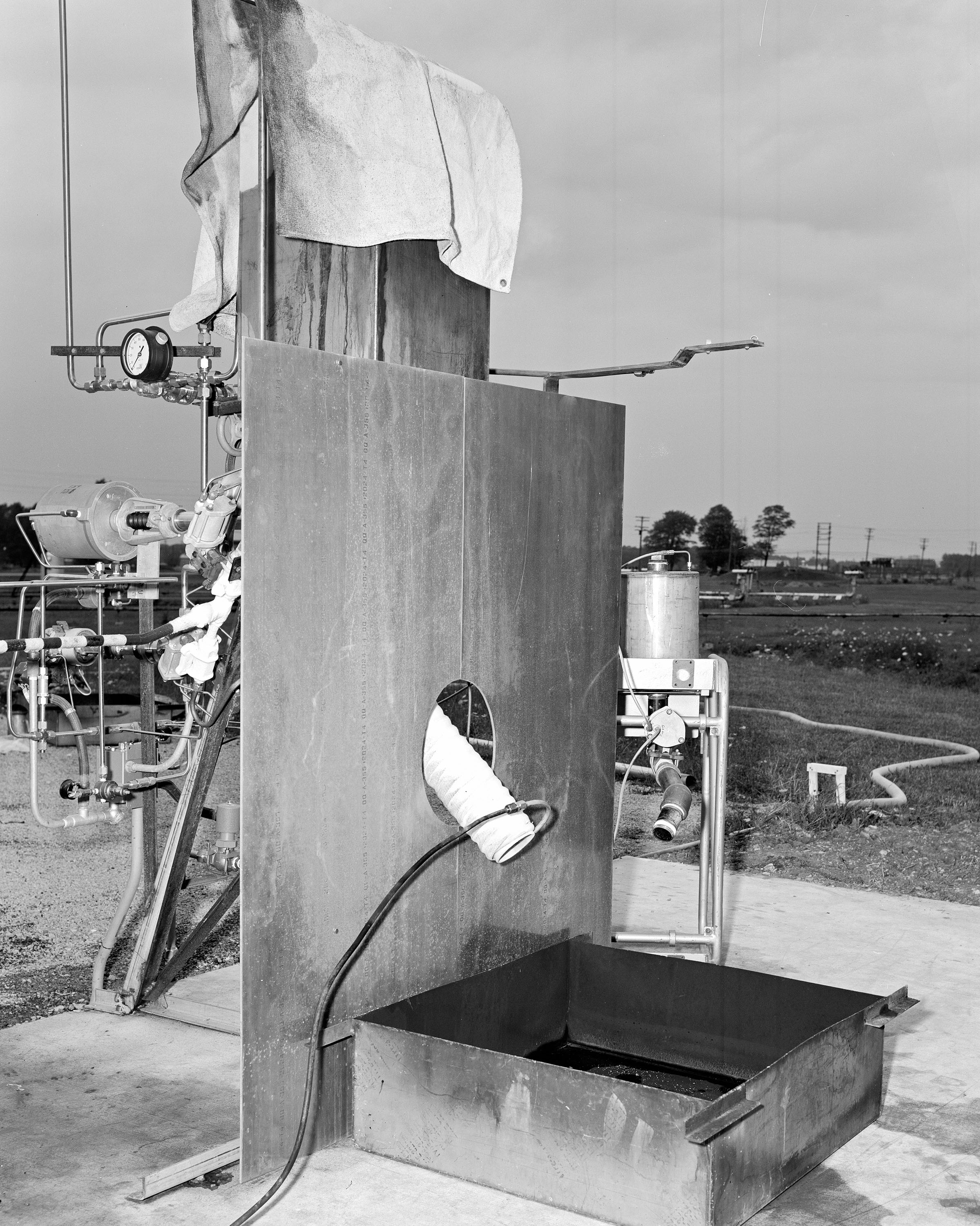
In the 1960s rocket designers were interested in using liquid fluorine as anoxidizer paired with the liquid-hydrogen fuel. Fluorine was lighter and produced more energy than the traditional liquid oxygen, but it was extremely toxic and volatile. Researchers used the large test chamber at J–5 to study the ability of certain seal materials to withstand exposure to high-power fluorine or fluorine/oxygen flow present in turbopumps. They also erected an external stand at J–5 to investigate the effect of a fluorine spill on various materials commonly found at launch sites, including sand, gravel, water, and other fuels. Some interactions yielded fiery explosions and others lingering toxic fumes. The researchers identified charcoal as a good mitigation tool.
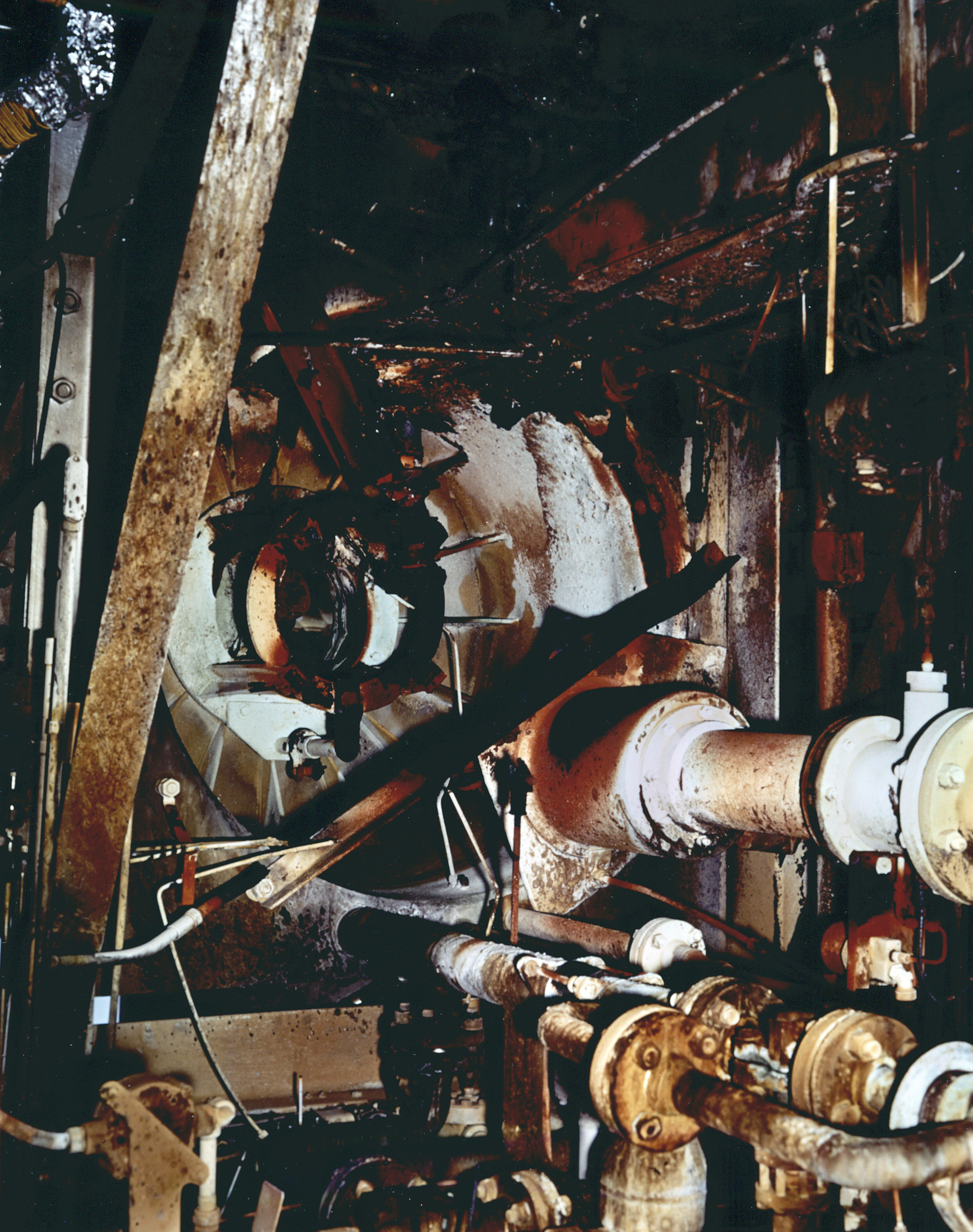
Researchers from Lewis and Pratt & Whitney used the Fluorine Pump Facility (I Site) to investigate the use of liquid fluorine in turbopumps. Lewis conducted a multiyear study of a centrifugal pump with an inducer to improve performance in cavitating conditions and seals made from Kentanium (tungsten carbide) K–162B (Kennametal Inc.). Despite an explosion that gutted I Site, the program successfully demonstrated that cavitation would not be a significant problem for fluorine pumps. Pratt & Whitney testing in I Site demonstrated that fluorine could be substituted for oxygen in the turbopumps for their successful RL–10 engines. Despite Lewis’ overall success with liquid fluorine, there have been no commercial fluorine rocket engines to date.
Documents
- Handling of Fluorine Mixtures in Rockets (1967)
- Compatibility of Materials with Fluorine Mixtures (1966)
- Reaction of Spills of Fluorine upon Various Materials (1966)
- Operation of Liquid Fluorine Pump in Cavitating Flow (1968)

Propellant Tank Durability
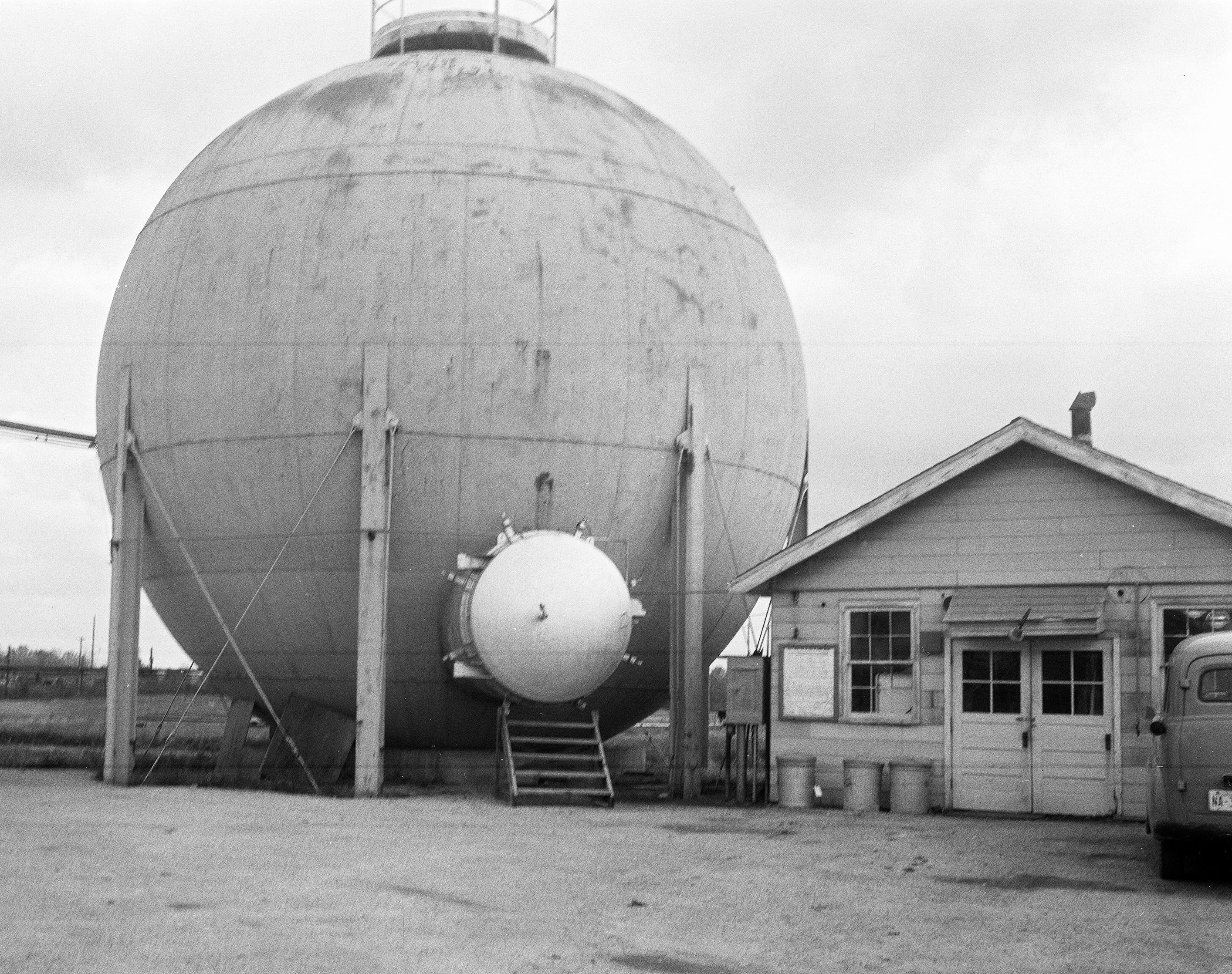
Lewis researchers used Rocket Systems Area facilities to study tank durability, pressurant variations, and insulation systems for both spacecraft and proposed in-space fuel depots. Rocket designers sought to minimize the weight of the fuel tanks while maximizing their strength. Stainless steel and steel alloys were the preferred materials for cryogenic fuel tanks in the 1960s. The most common method of testing a tank’s durability was referred to as cold shocking. The tank was filled with liquid nitrogen or another stable cryogenic fluid. The staff then emptied the tank and checked to see if the cold temperatures affected any of the welds, couplings, or lines.
Engineers used several of the Rocket Systems Area’s sites to cold shock a variety of propellant tanks during this period. This was sometimes at the request of the manufacturer, sometimes to check the tank before performing another type of test, and sometimes to recheck it after a test run. The cold shock tests included Centaur tanks in the Hydraulics Laboratory (F Site) and Vacuum Environment Facility (J–3), the Arthur D. Little tanks at Tank Test Facility (J–4) and Cryogenic Propellant Tank Facility (K Site), and a variety of tanks ranging from 5 to 13 ft in diameter at K Site.
Tank Pressurization
Liquid-fuel propellant tanks use a heavy gas to force the fluid out towards the turbopump. Too much of this pressurant gas would require thicker tank walls, adding to the vehicle’s weight. Not enough gas would slow the flow of the cryogenic fluid, resulting in boiling or cavitation.
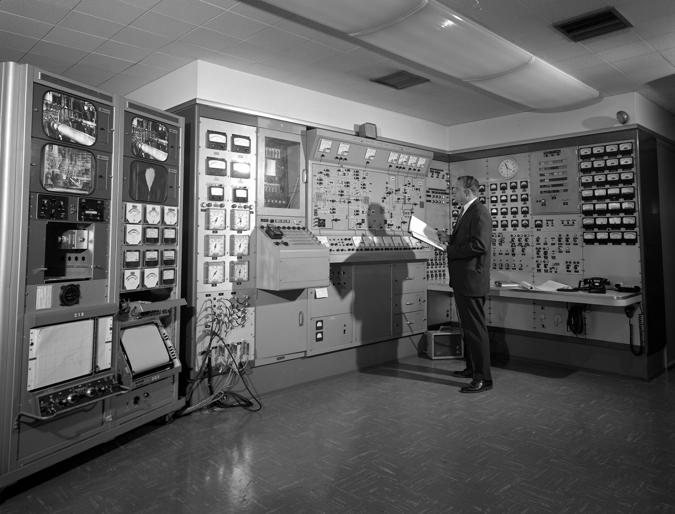
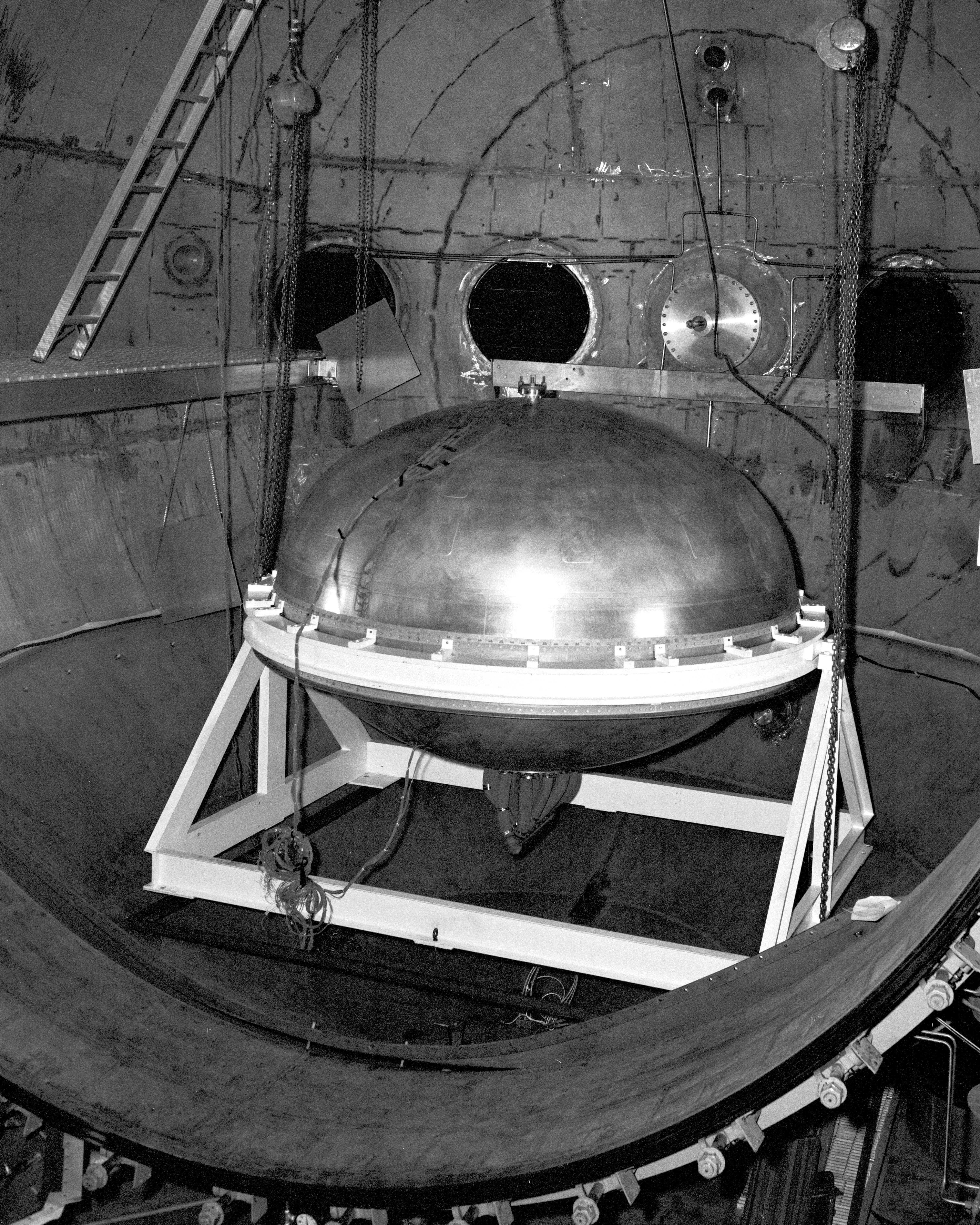
Lewis researchers used K Site to study the performance of several pressurizing gases and injectors and to determine the effect of internal temperatures on cryogenic propellant tanks. The staff installed the tank in the test chamber, filled it with liquid hydrogen, adjusted the temperature, introduced the pressurizing gas, and measured the resulting hydrogen flow from the tank. They varied the injector types and temperatures, introduced vibrations to the tests, and changed the type of gas. The K Site tests assisted Lewis researchers in refining their predictive tools. The researchers also compared the performance of different pressurizing gases in tanks containing liquid methane.
Lewis also initiated a study on the necessity of boost pumps for the Centaur propellant flow system. These pumps accelerated the propellant flow from the tank to the turbopump but also increased the vehicle weight. Researchers conducted tests at the High Energy Rocket Engine Research Facility (B–1) test stand to determine if improved pressurizing gas performance eliminated the need for the boost pumps.
Reports
- Pressurant for Discharge of Methane From Tank (1974)
- Hydrogen Discharge of Hydrogen From 5-foot Tank (1969)
- Helium Discharge of Hydrogen From 5-foot Tank (1970)
- Hydrogen Discharge of Hydrogen From 13-foot Tank (1969)
- Helium Discharge of Hydrogen From 13-foot Tank (1970)

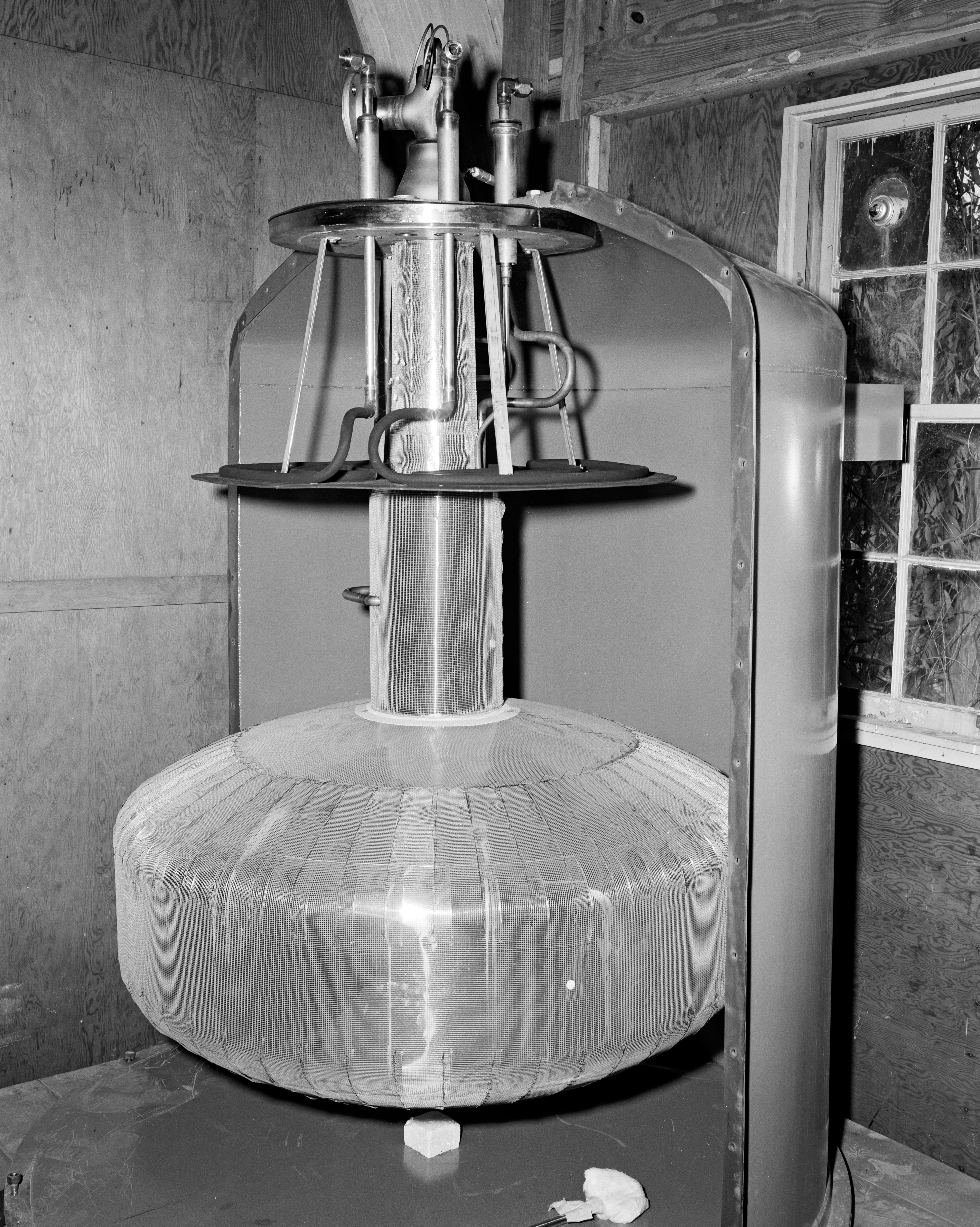
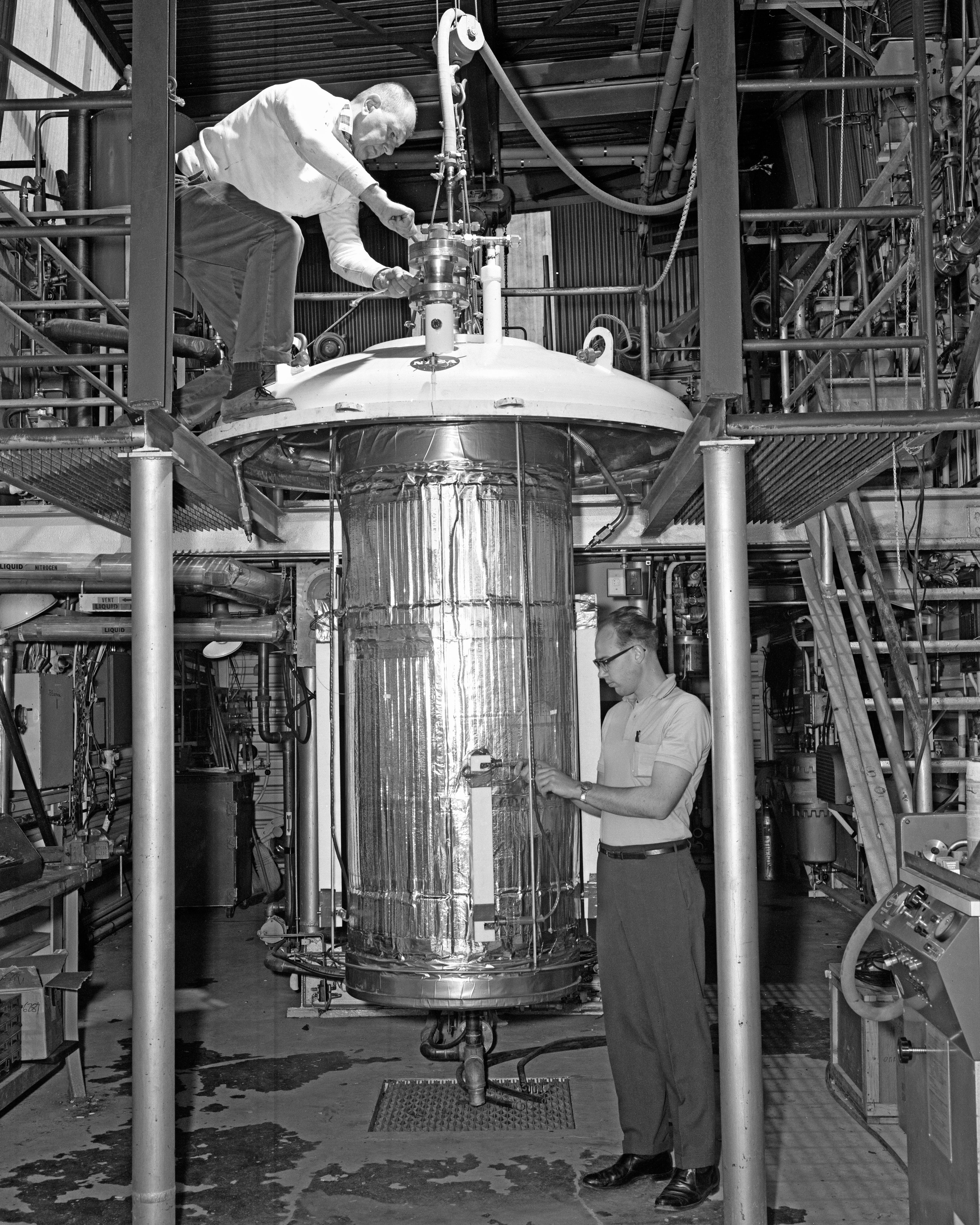
Tank Insulation Systems
NASA researchers used the Rocket Systems Area sites to examine methods for insulating cryogenic propellant tanks to prevent fuel evaporation during launch and over time in space on long-duration missions. Even minor temperature increases could lead to the loss of enough fuel to cause a mission failure. By the early 1960s engineers determined that foam or multilayered aluminum was sufficient for short-term missions, whereas the use of shields to block solar radiation were the key to storage on long-term missions.
Lewis analyzed multilayer insulation systems designed by the Linde and Arthur D. Little corporations at J–3 and Tank Test Facility J–4. The former consisted of an aluminum and fiberglass layer encapsulated in an aluminum and Mylar jacket; the latter was a gold, Mylar, and aluminum layer separated by mesh silk layers. They also investigated the use of multilayer insulation shaped into removable blankets. The study provided information on methods of applying the blankets to the tank and the optimal number of layers to include. Lewis researchers also developed a unique self-evacuating multilayer insulation (SEMI) to prevent air from contacting the tank during ground holds. They verified SEMI performance at K Site.
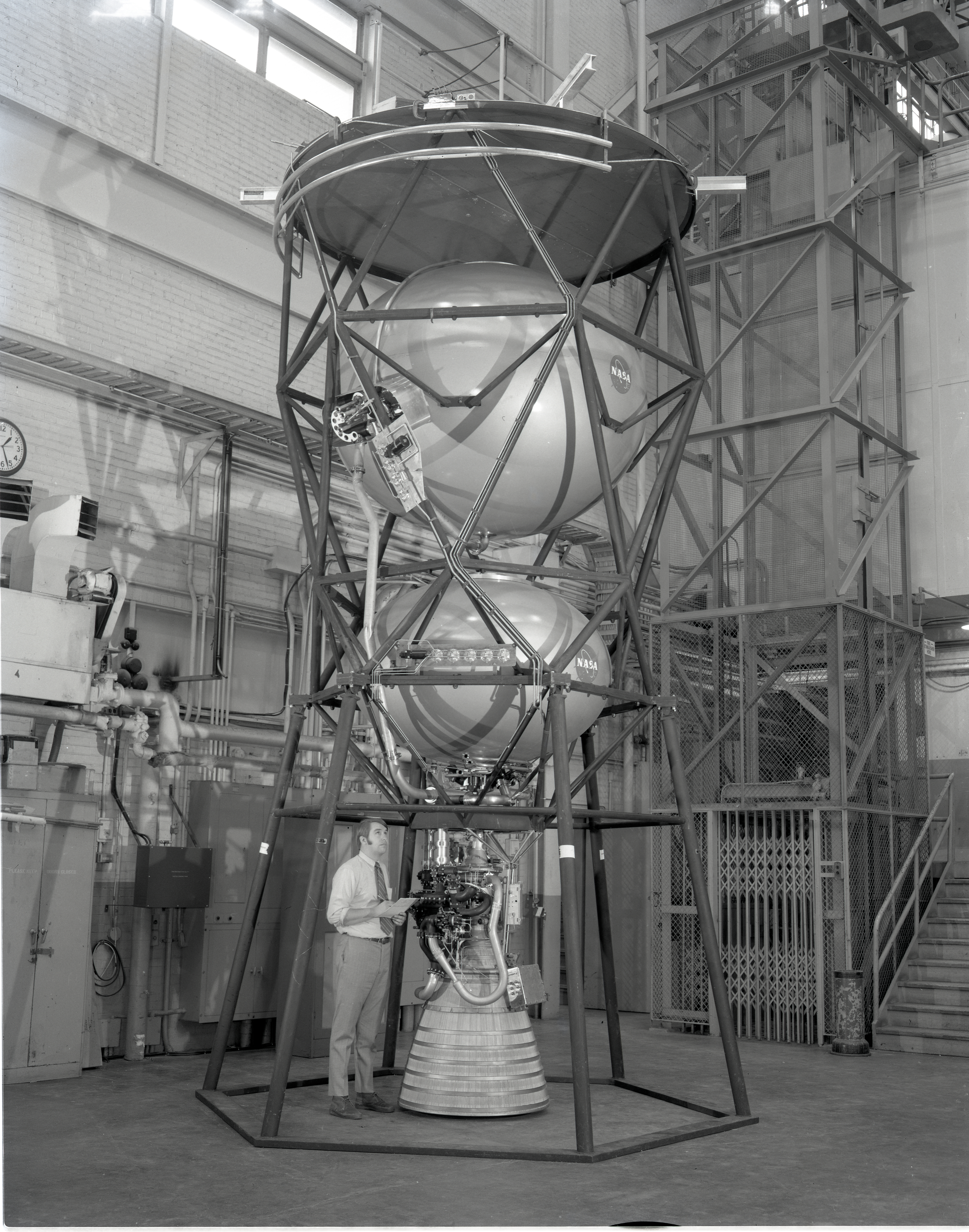
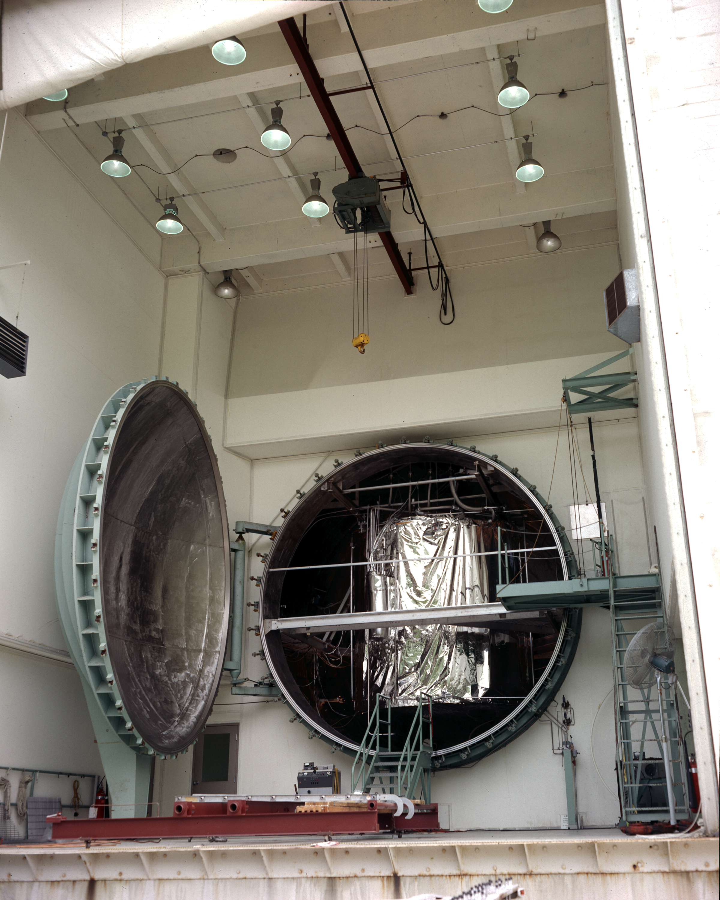
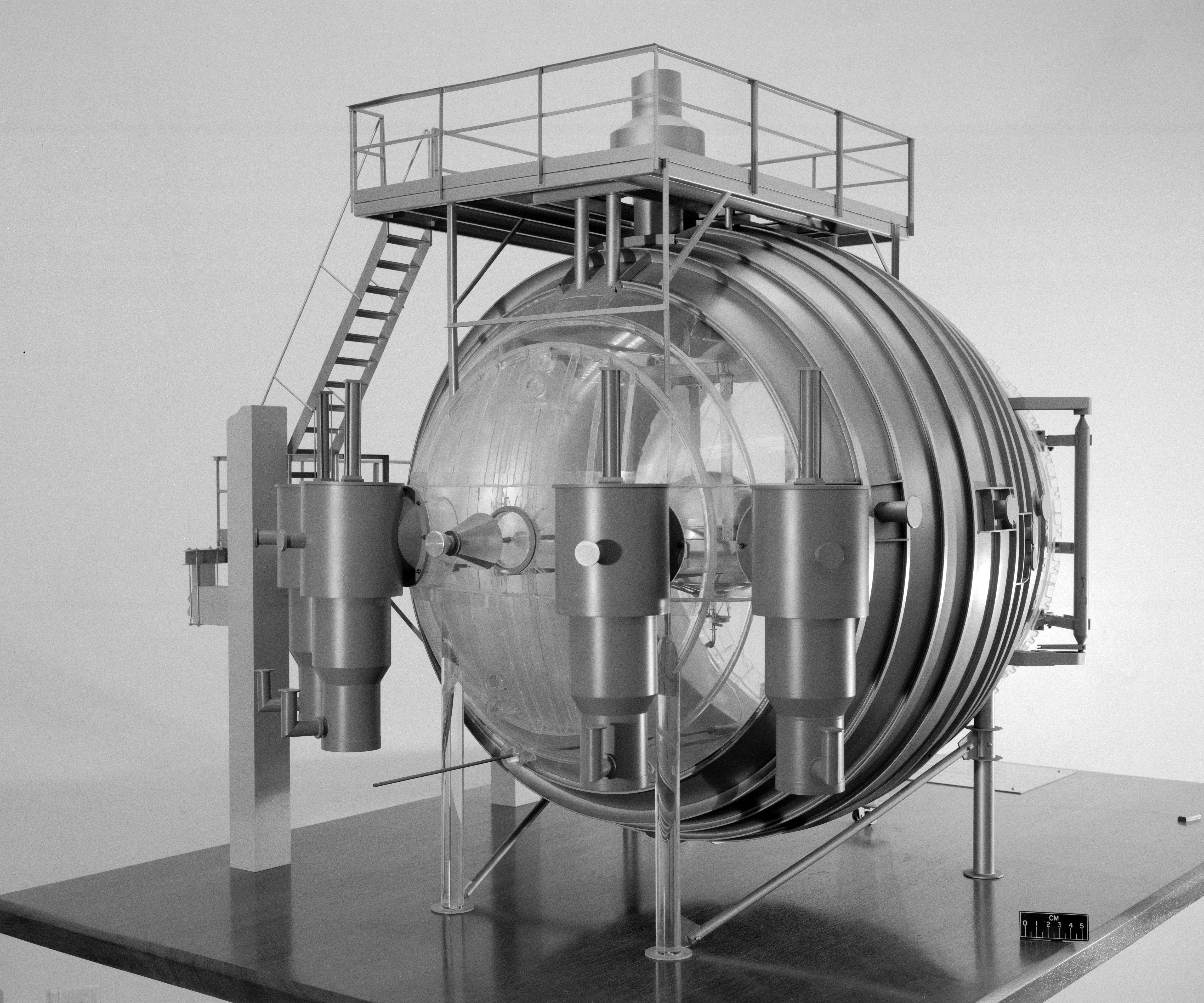
Lewis researchers designed a Cryogenic Storage Test Vehicle to study the integration of shadowshields (which blocked solar radiation) and multilayer insulation into a realistic tanking system for long-duration missions. The vehicle included hydrogen and oxygen tanks, a simulated engine, and a nozzle. The researchers installed the vehicle in the K Site test chamber with a cold wall to simulate temperatures in space. They then verified the system’s performance in simulated near-Earth and deep space conditions.
Documents
- Compressed Multilayer Insulation System for Rocket (1963)
- Study Under Groundhold Conditions of Insulation Systems(1965)
- SEMI Prefabricated Panels for Cryogenic Tanks(1968)
- Lightweight, Self-Evacuated Insulation Panels (1970)
- Multilayer Insulation Containing 20 to 160 Layers (1974)
- Performance of Replaceable Multilayer Insulation(1977)
- Integrated Thermal Protection for Long-Term Storage(1977)