Pump Sites
One of the biggest challenges facing the designers of early high-performance liquid rocket engine was pumping the cryogenic fuel and oxidizer from their tanks to the fuel injectors at high rates of speed. NASA Lewis Research Center research was key to the manifold increase in turbopump performance during the 1960s.
The Rocket Systems Area included several sites dedicated to turbopumps for cryogenic fluids. The Liquid Hydrogen Pump Facility (A Site) tested inlets and inducers for hydrogen and oxygen pumps, the Turbopump Facility (C Site) analyzed pumps in boiling hydrogen, the Controls and Turbine Facility (D Site) tested turbines that powered the pumps, the Pilot Plant (G Site) studied small-scale pump components, and the Fluorine Pump Facility (I Site) focused on liquid-fluorine pumping.
A Site – The Liquid Hydrogen Pump Facility
A Site was designed to testimpellers and inducersfor high-flow hydrogen and oxygen pumping systems. The facility included separate test loops for hydrogen and oxygen turbopumps. Researchers utilized these test loops to determine the performance of high-power turbopumps with experimental inducers and impellers in conditions comparable to those experienced when integrated into a liquid chemical rocket engine.
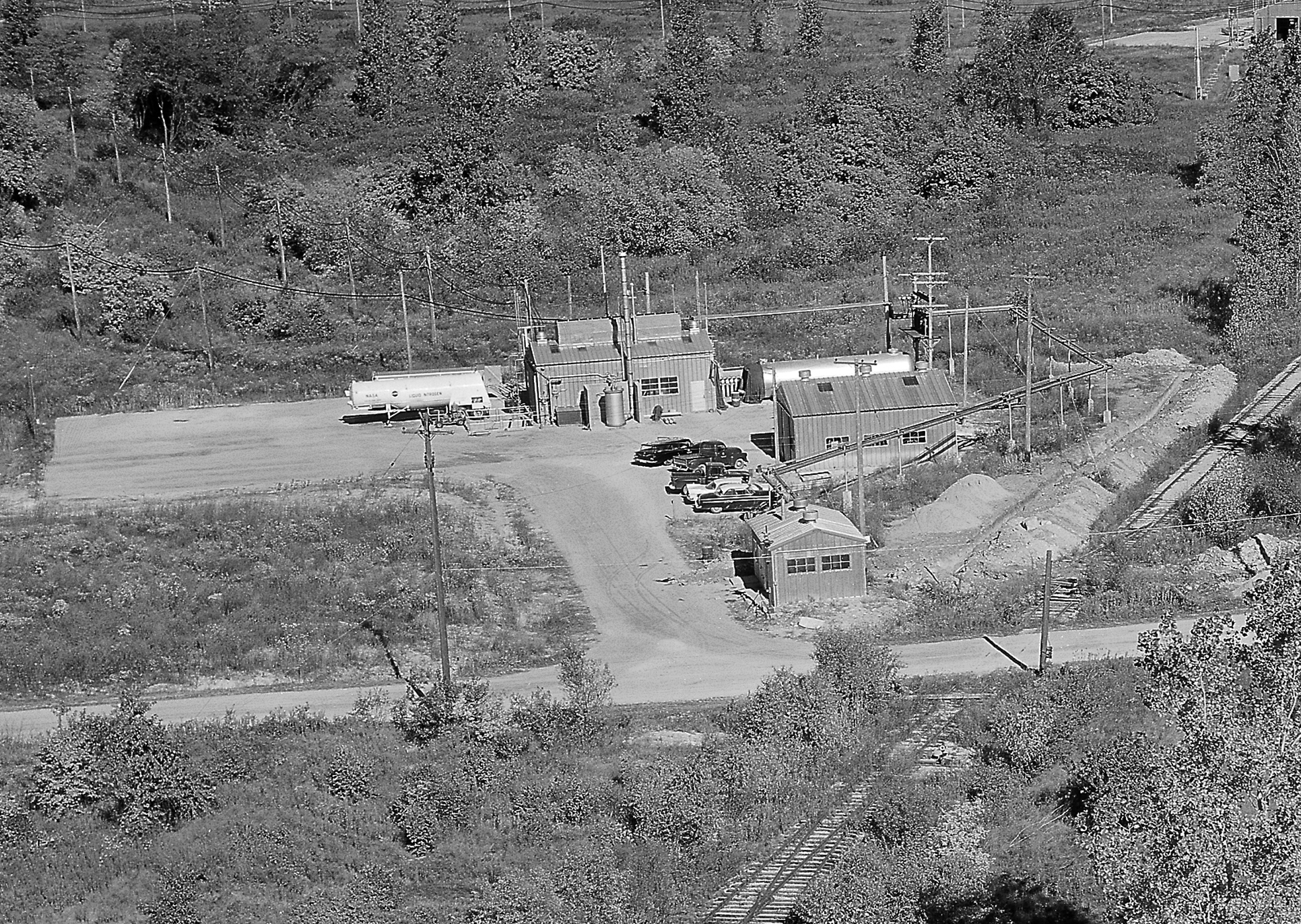
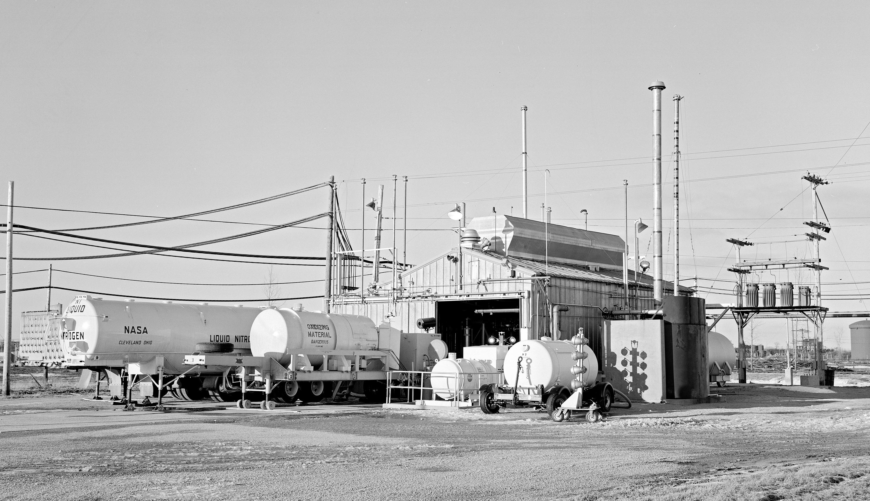
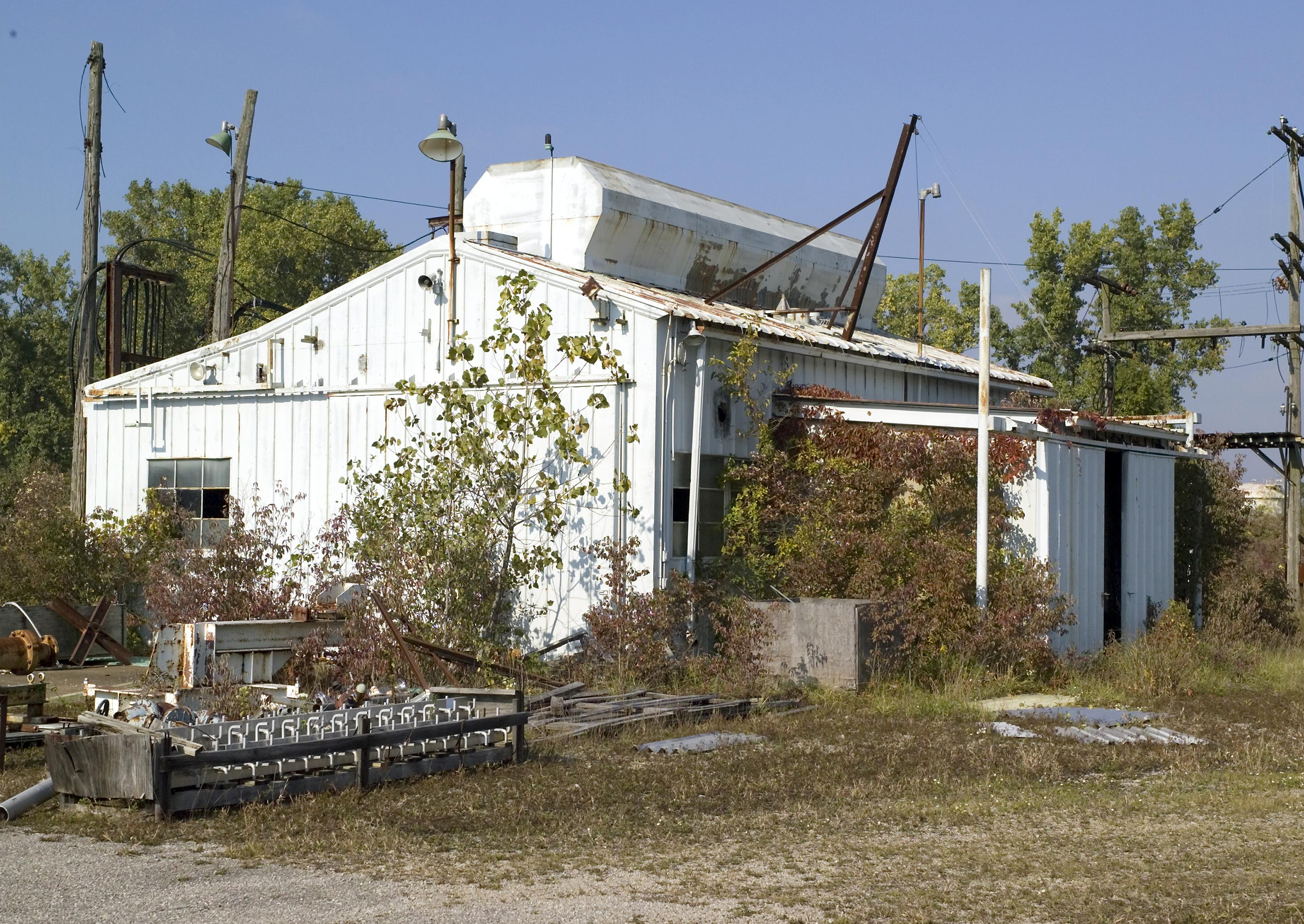
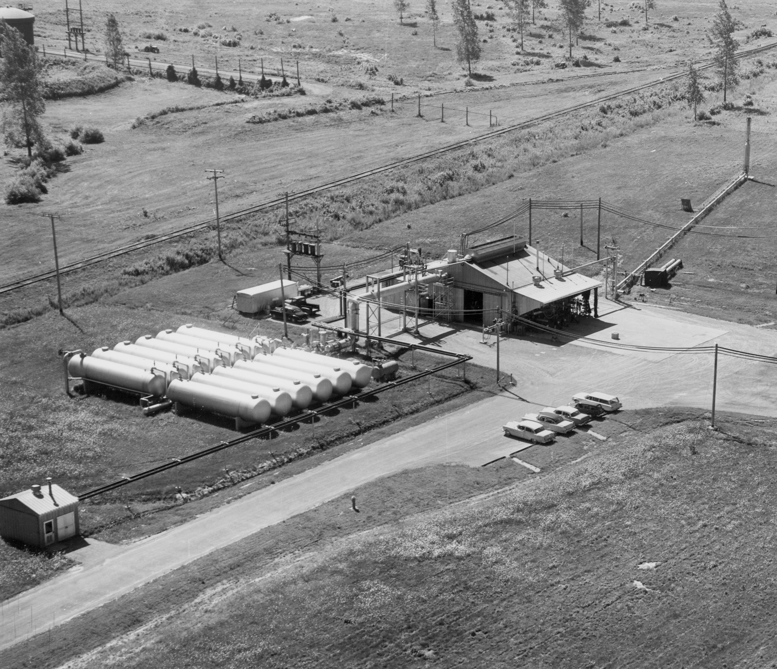
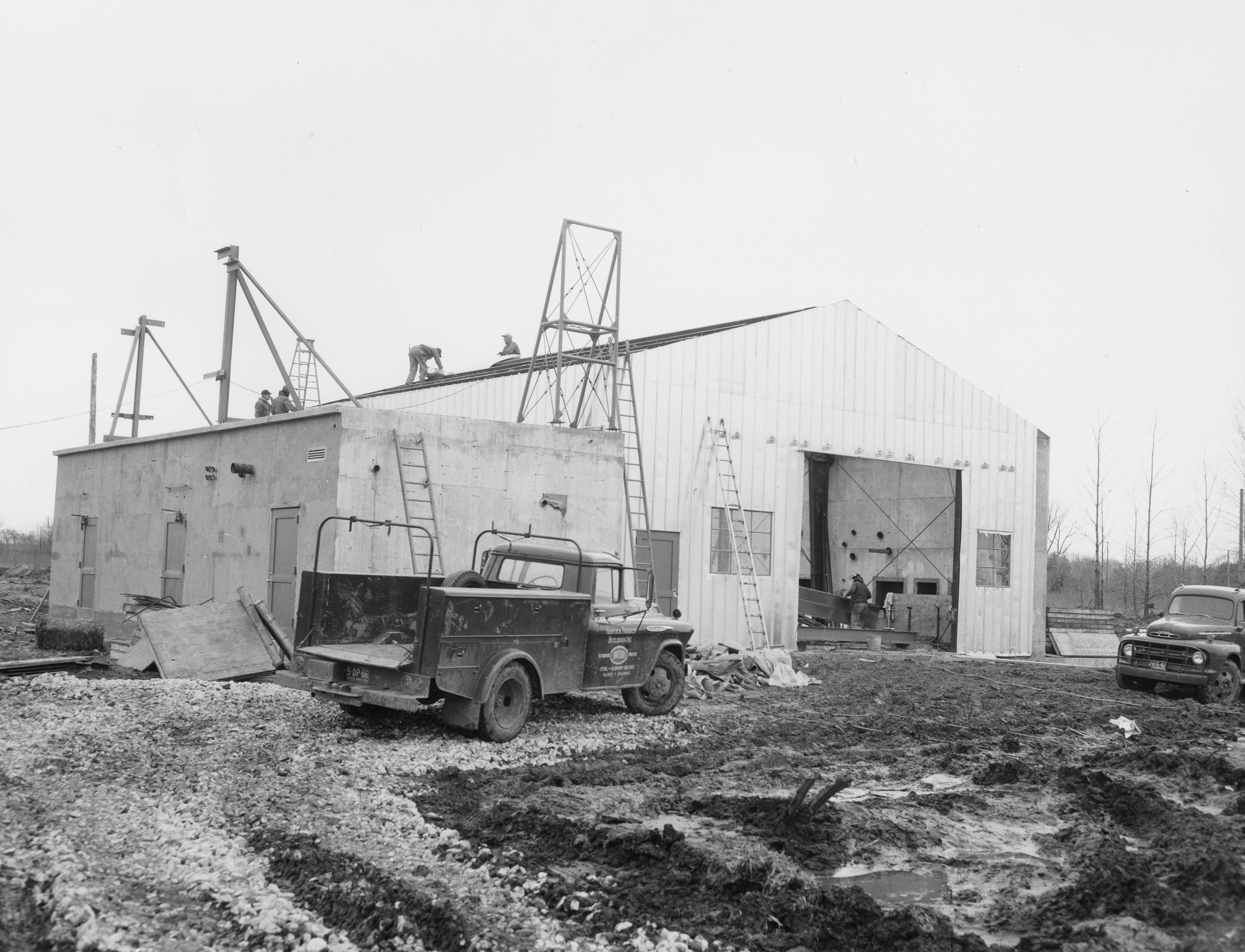
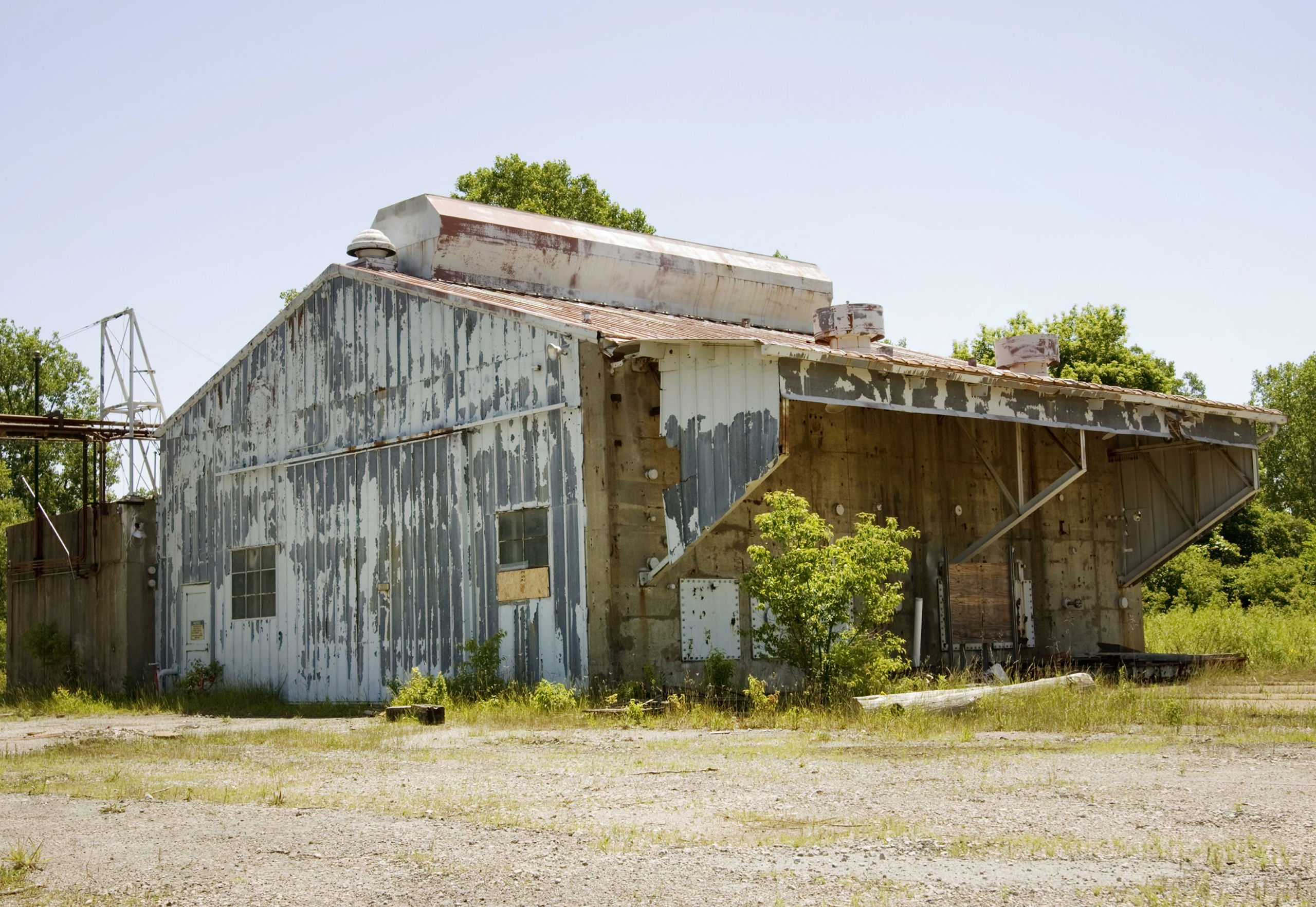
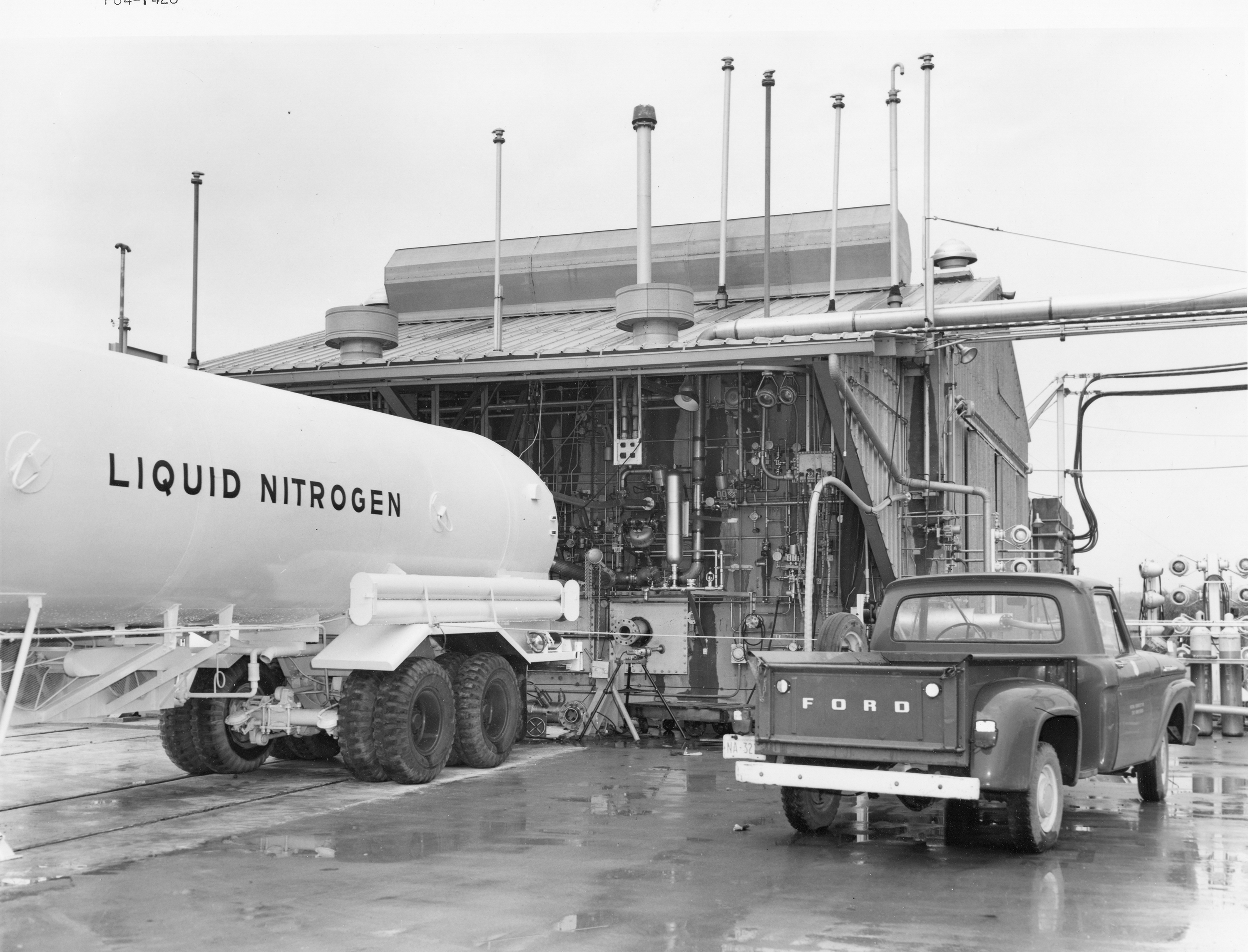
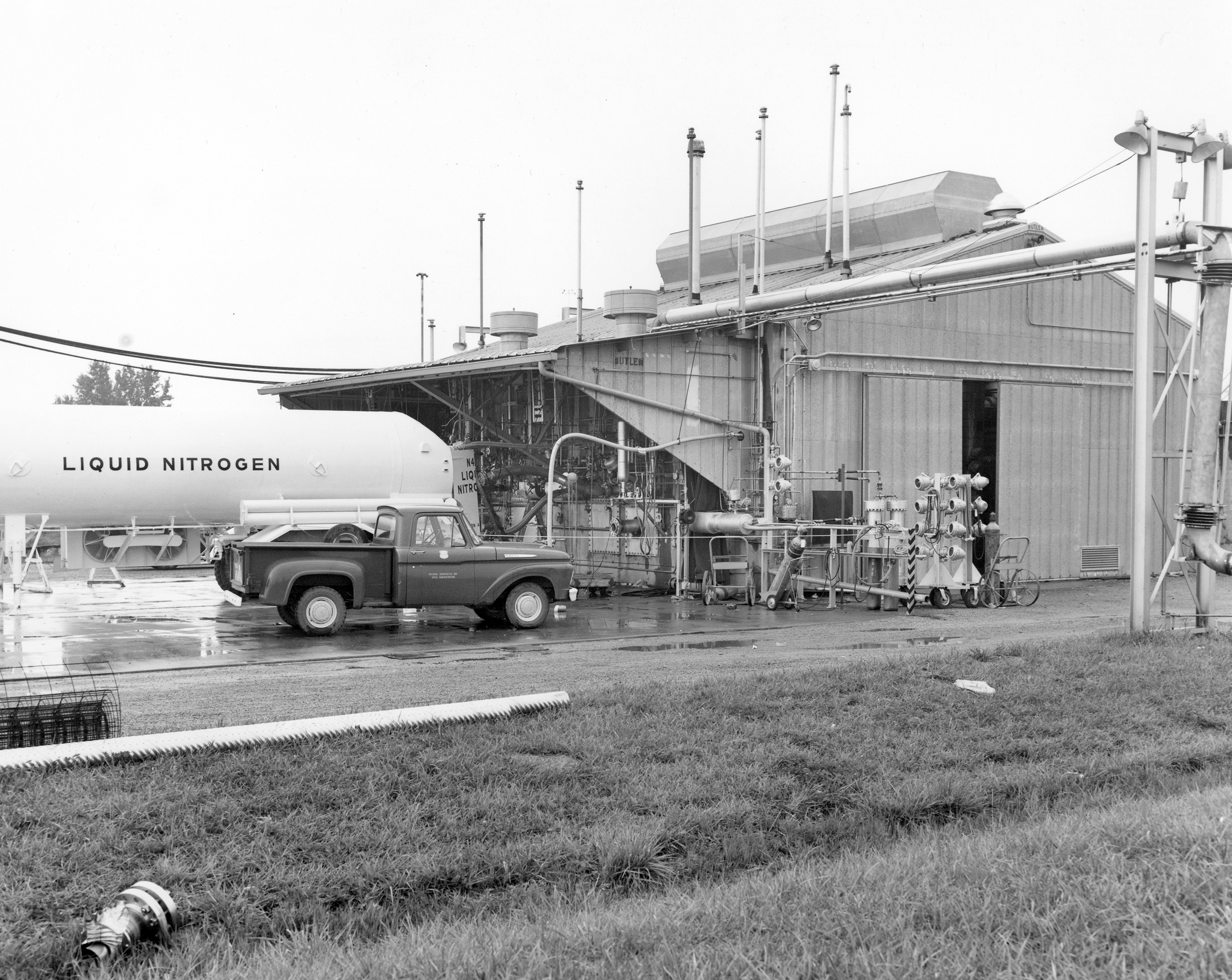
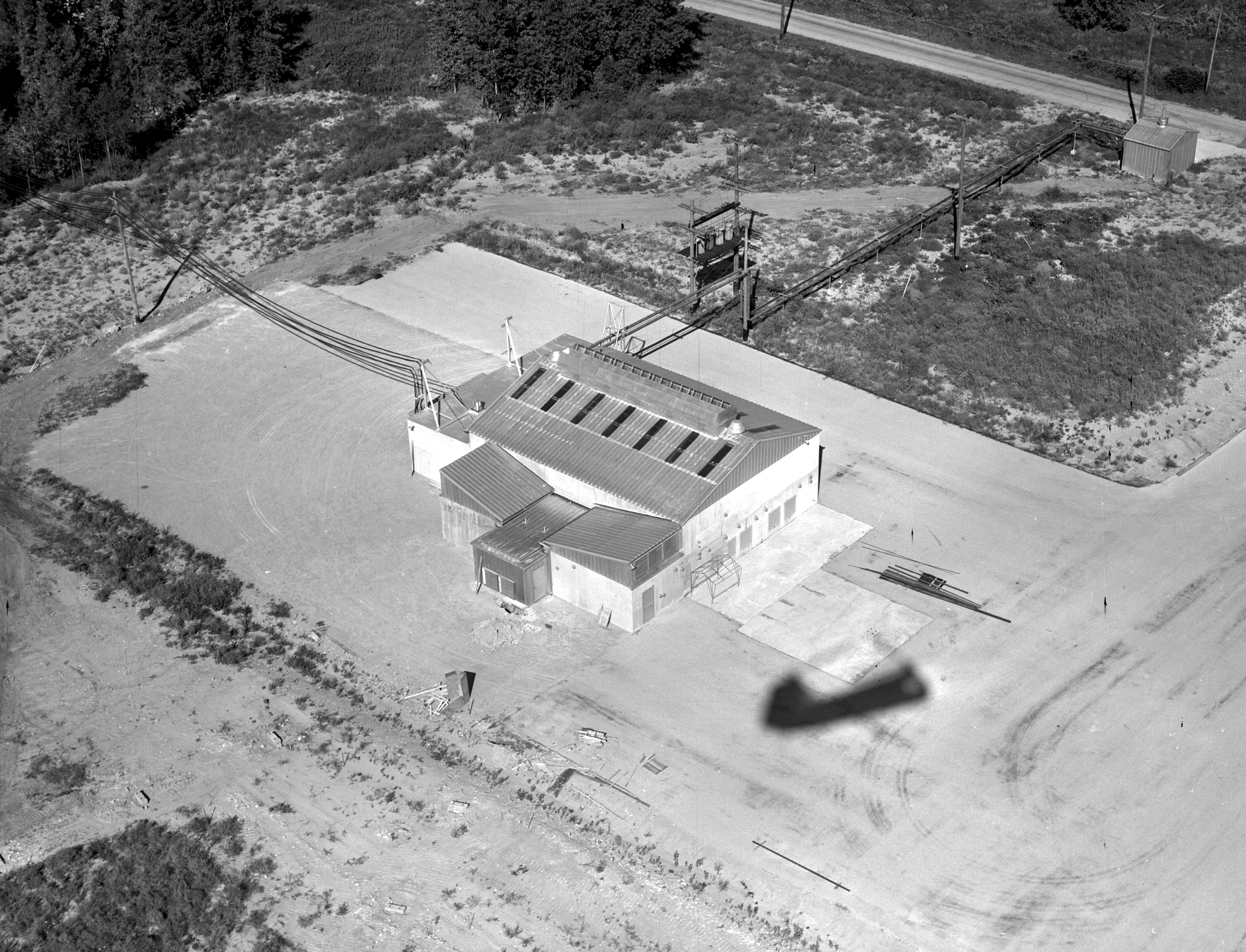
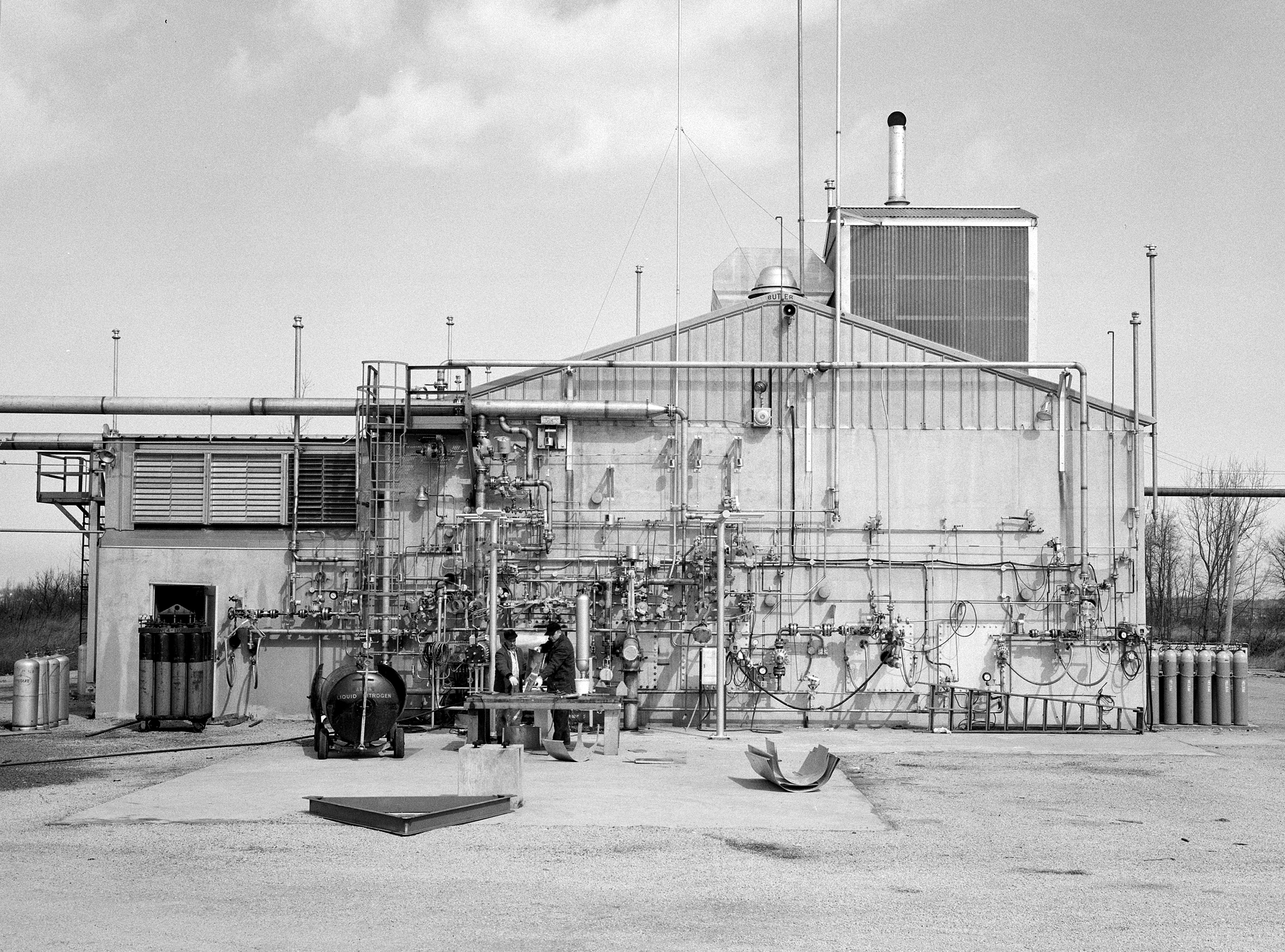
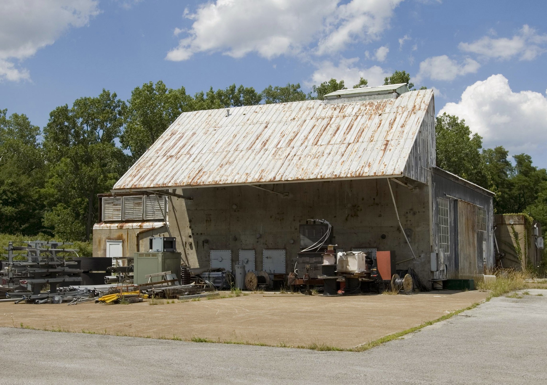
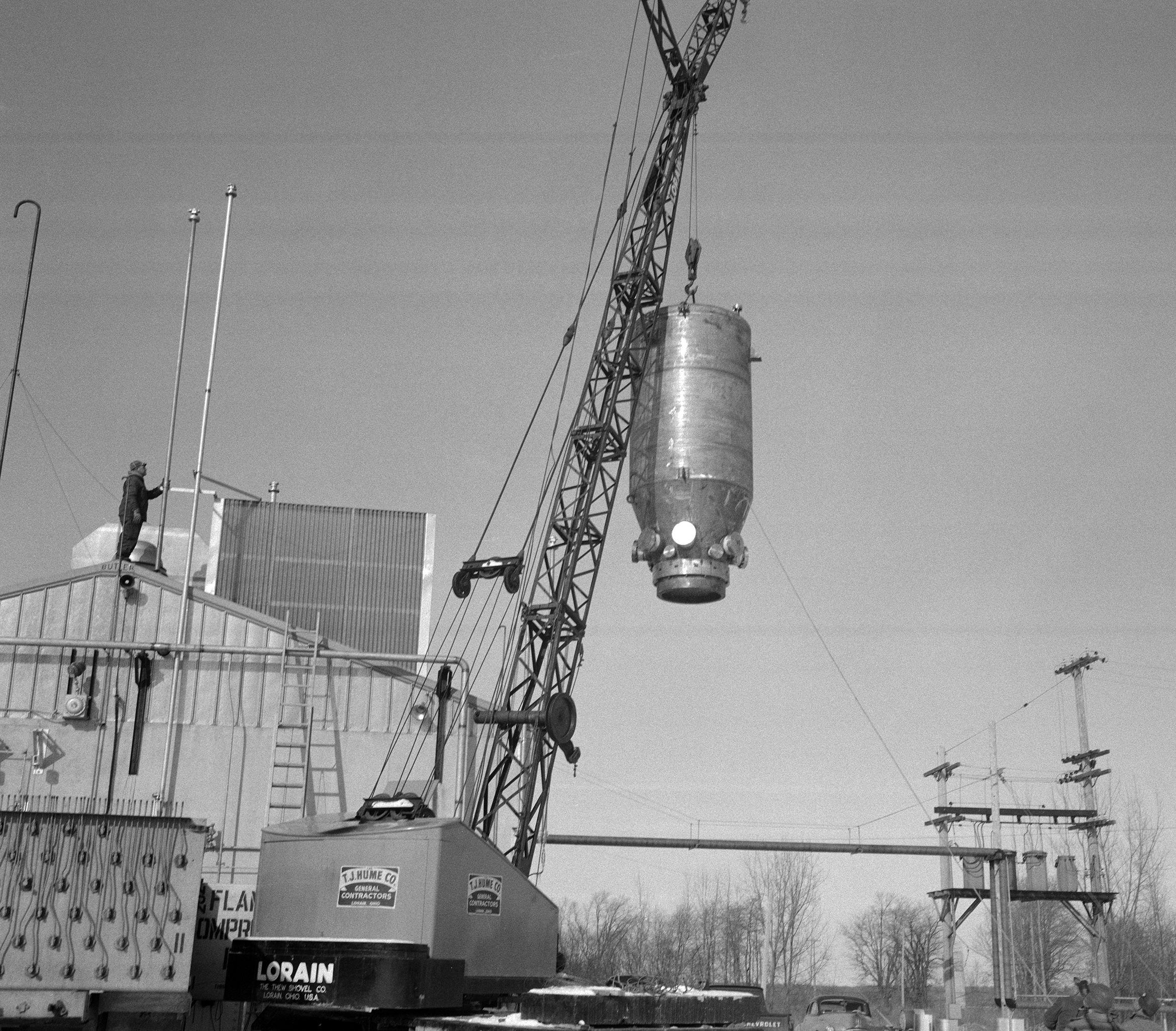
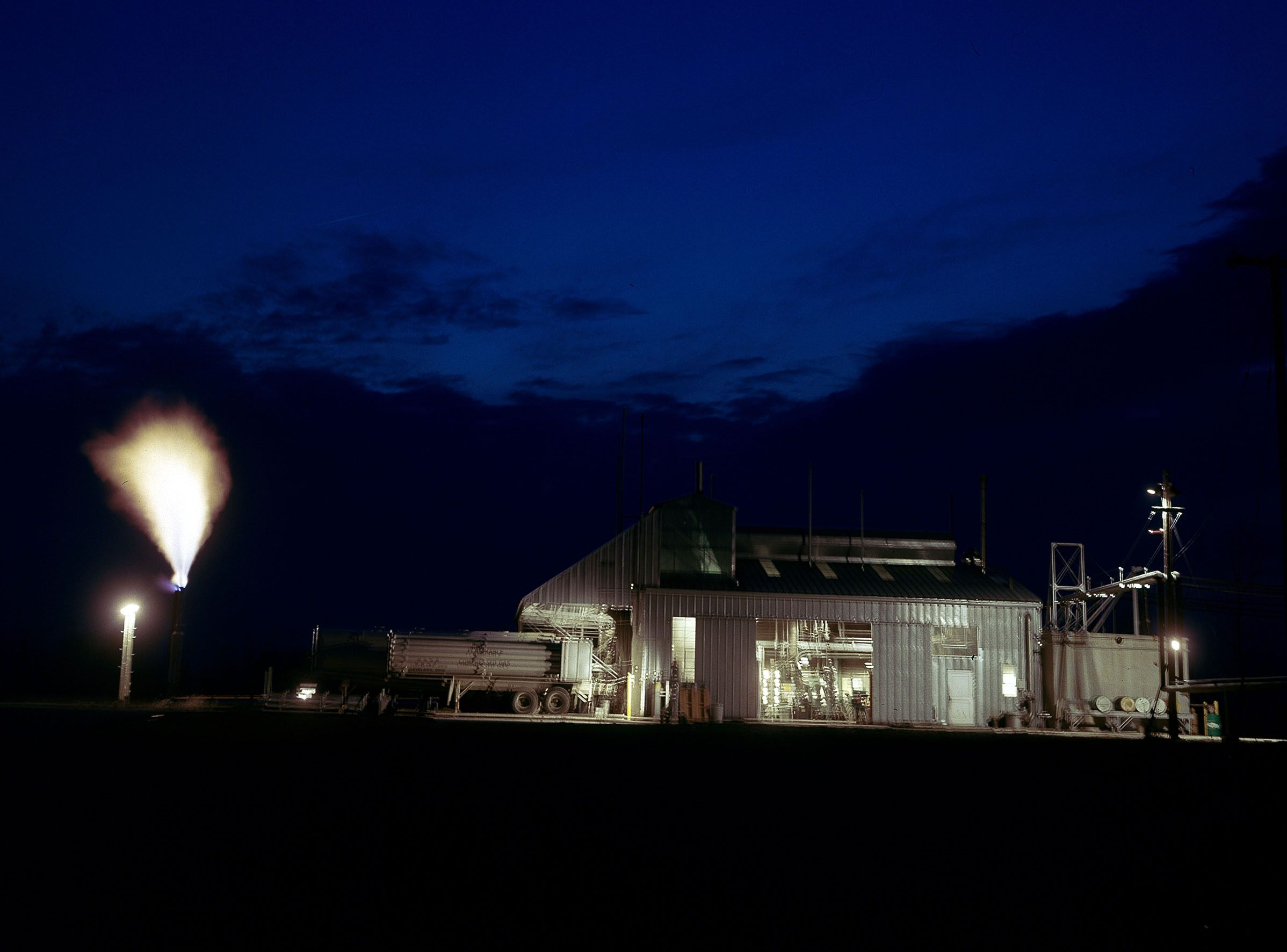
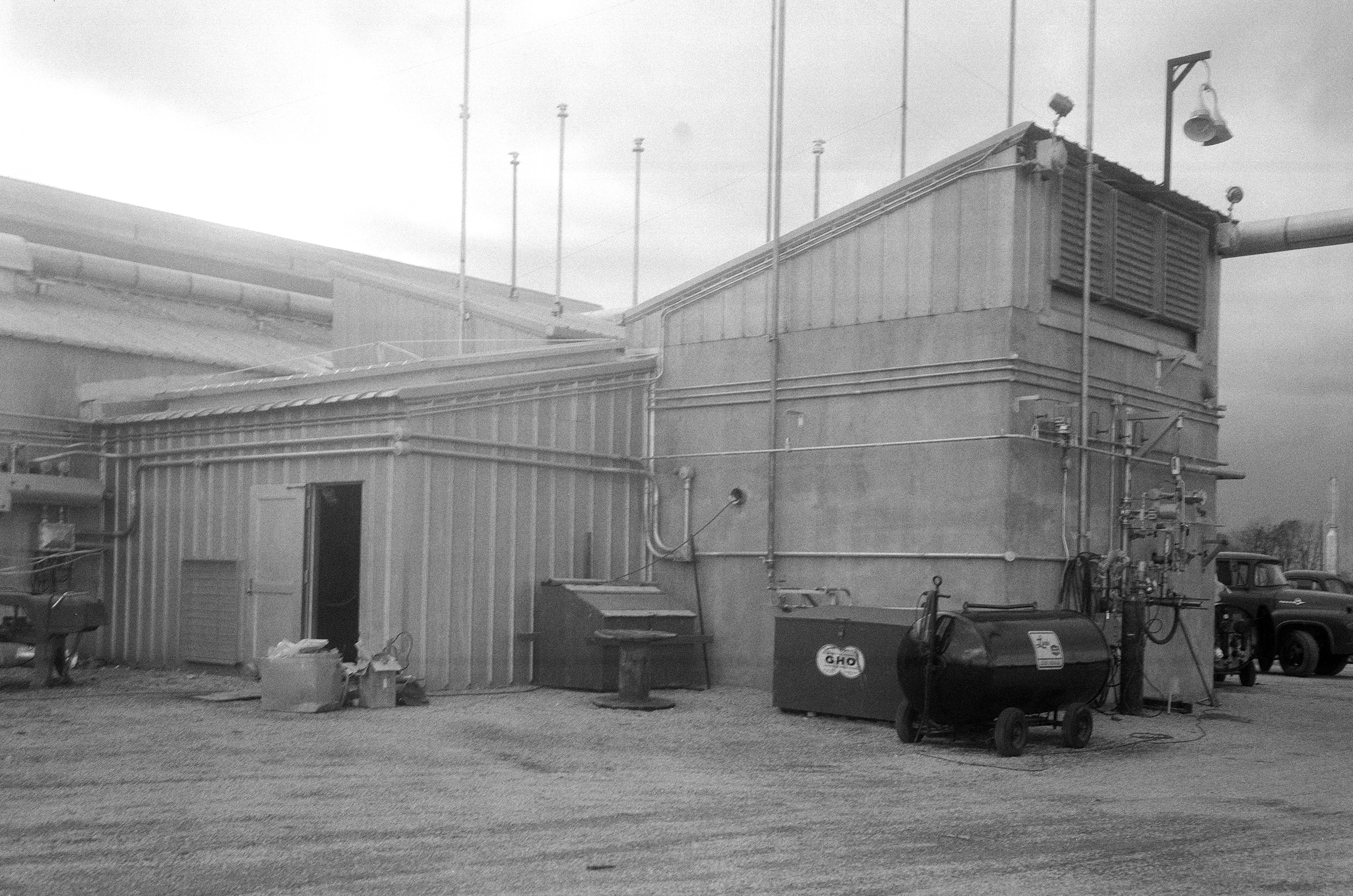
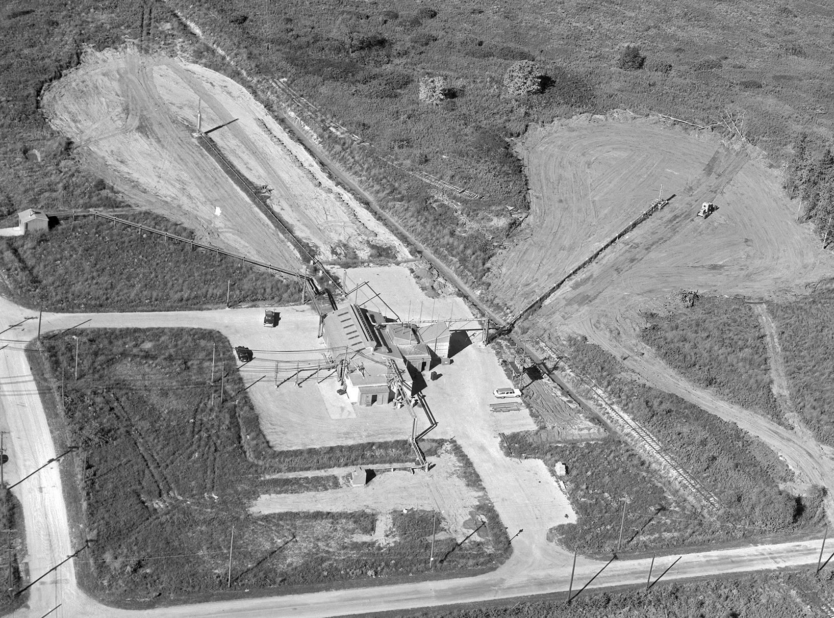
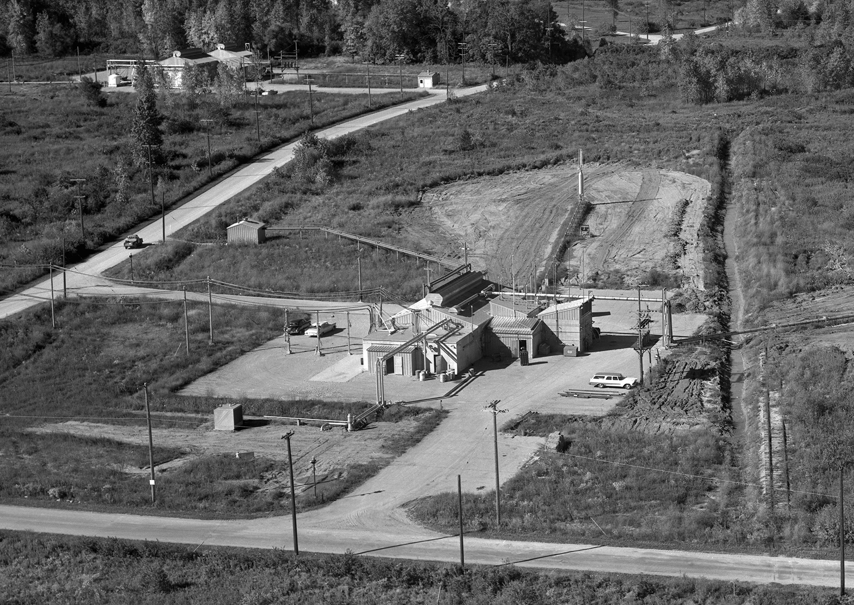
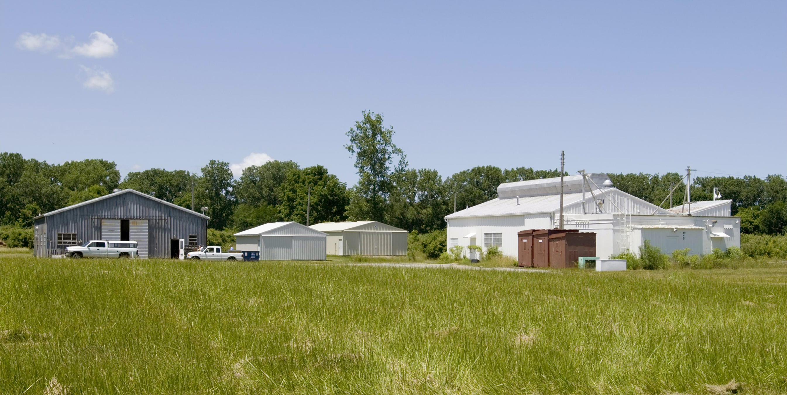
Physical Description: A Site was located on Fox Road near the northwest corner of the Rocket Systems Area. The A Site test loops were contained in a single 1,605-square foot Butler Building that included large access doors on the north and south ends and a 3-ton overhead crane. Hardware included gas turbines, gearboxes, and bedplates. An addition along the east wall contained an Instrument Room, Controls Room, and Electrical Mechanical Room. NASA added a large shop building just east of the facility to prepare test articles. Twelve tubular storage Dewars and a small pump house were located just north of the facility. Propellant trailers connected to the facility along the west wall, and a gaseous-hydrogen line ran south from the building to a small burnoff stack.
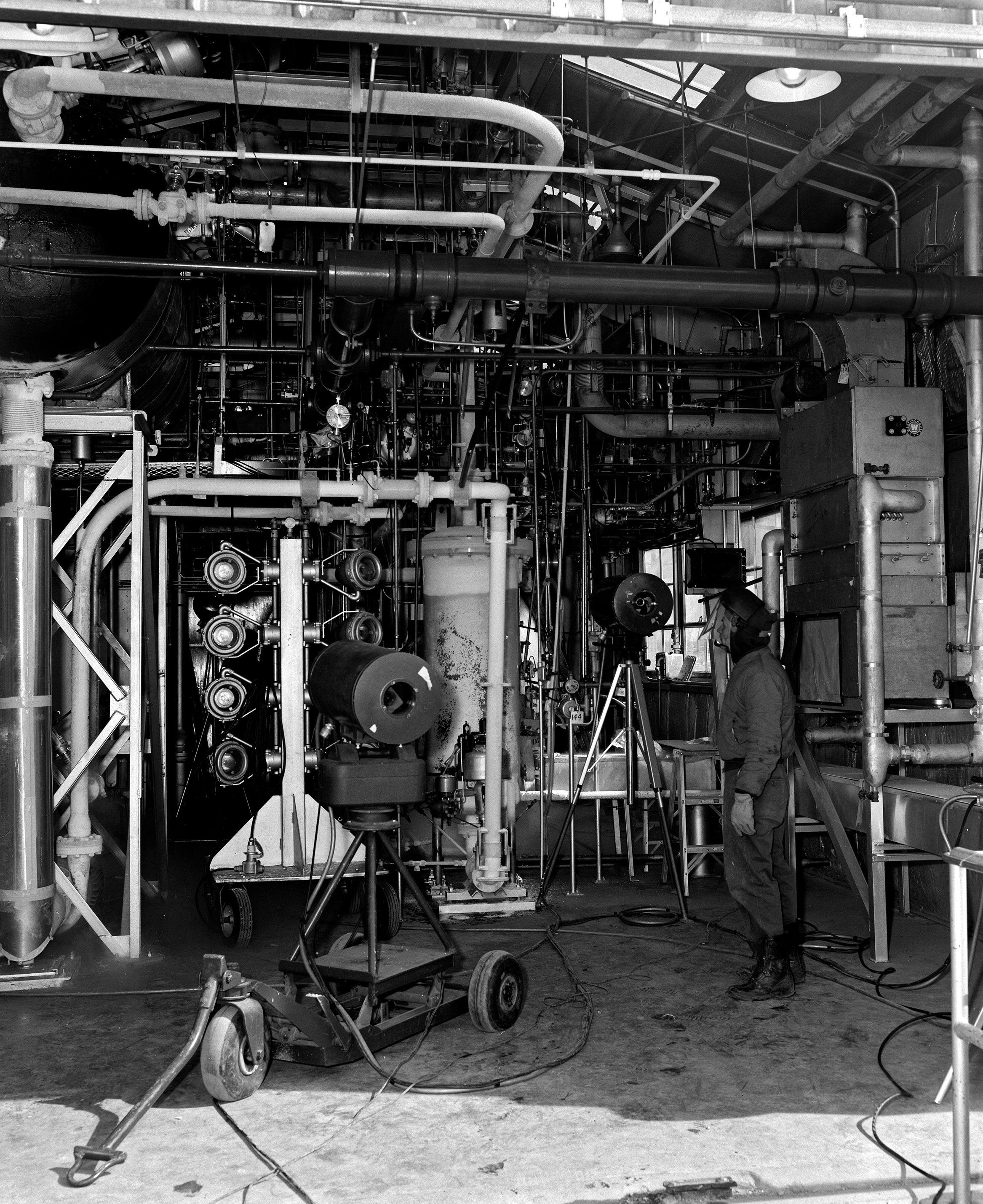
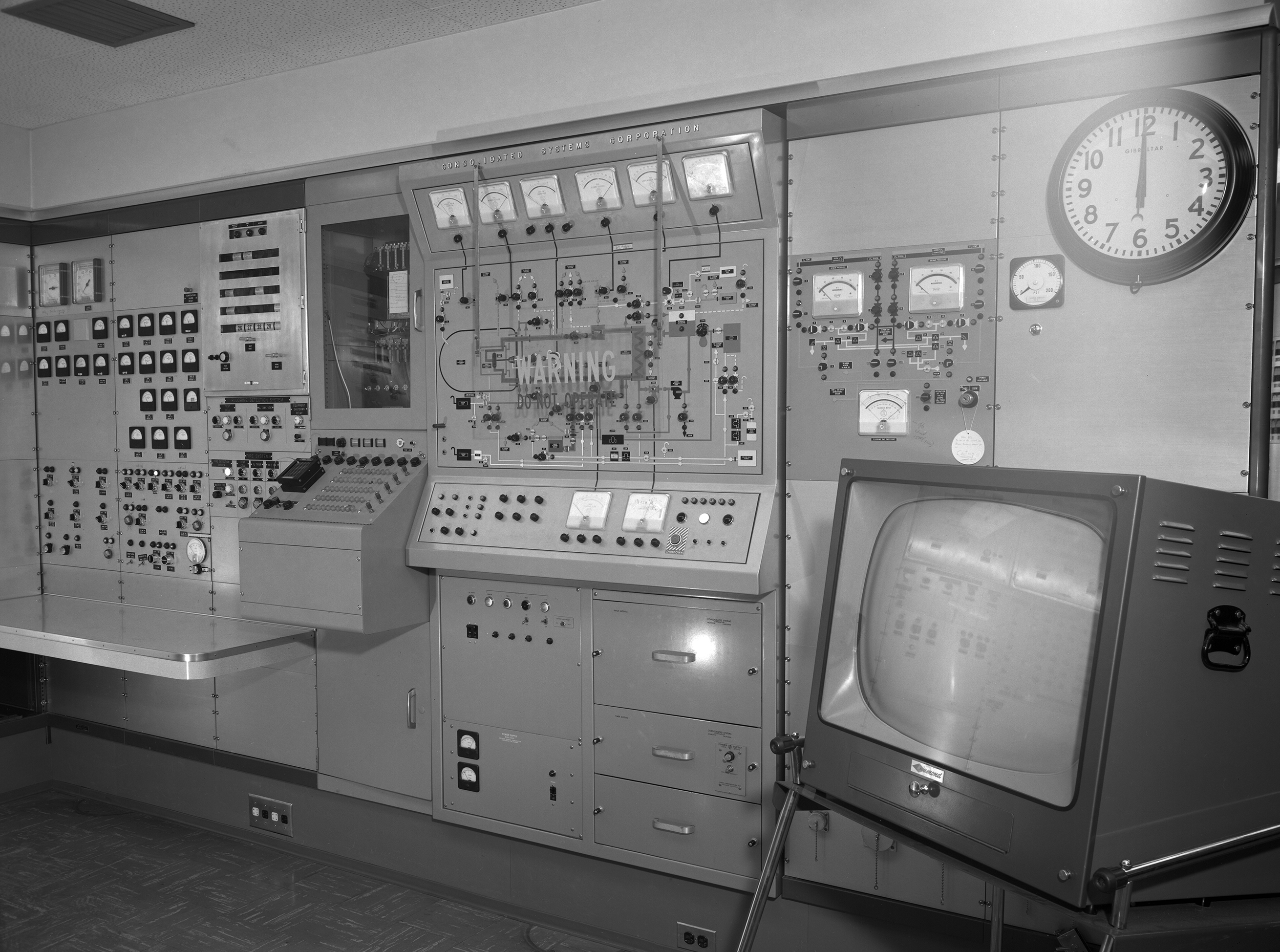
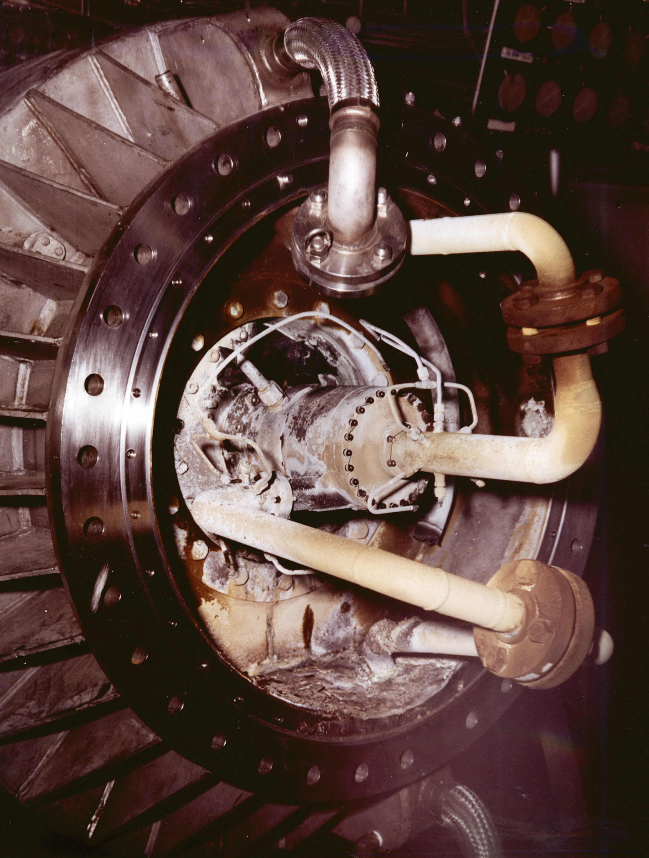
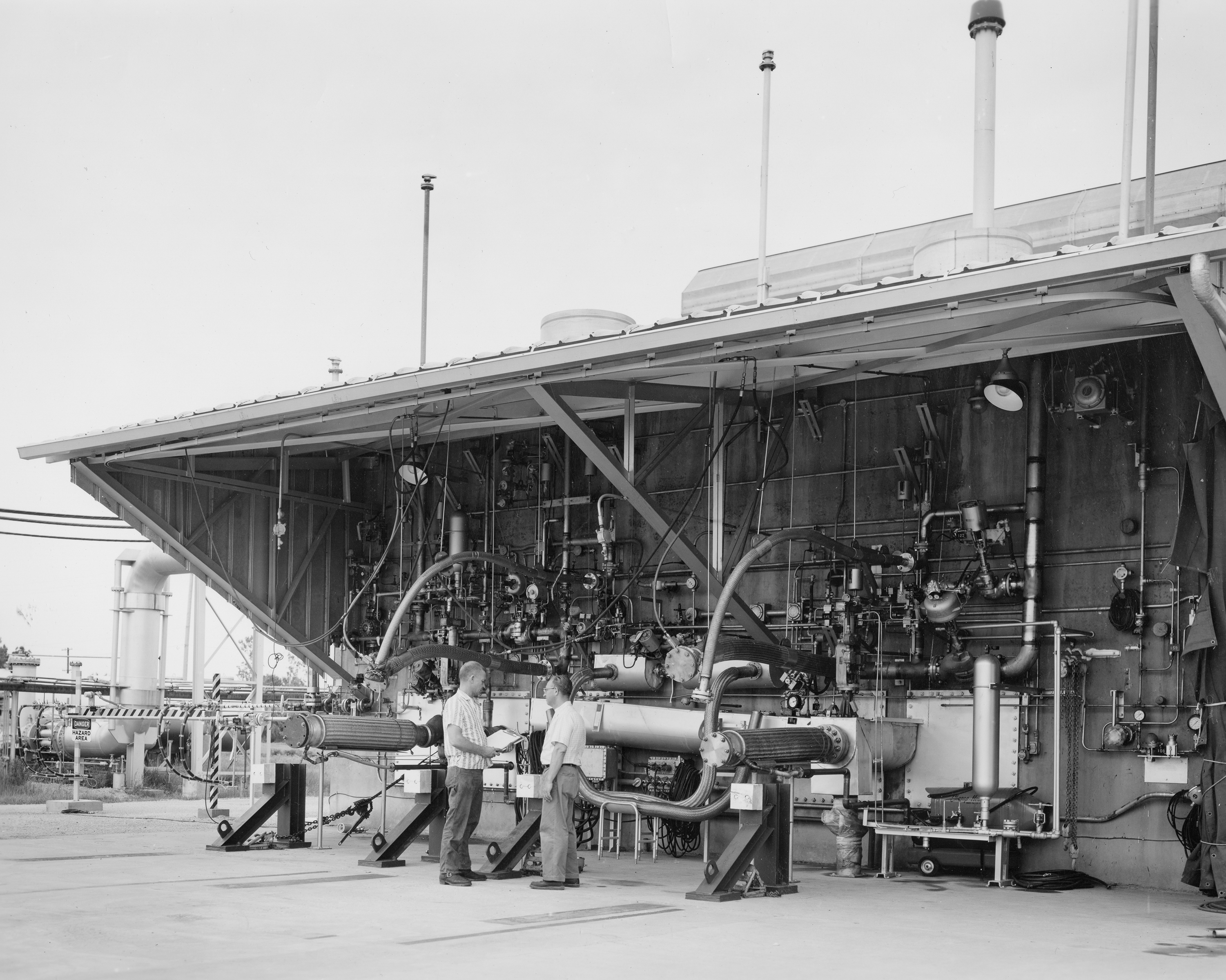
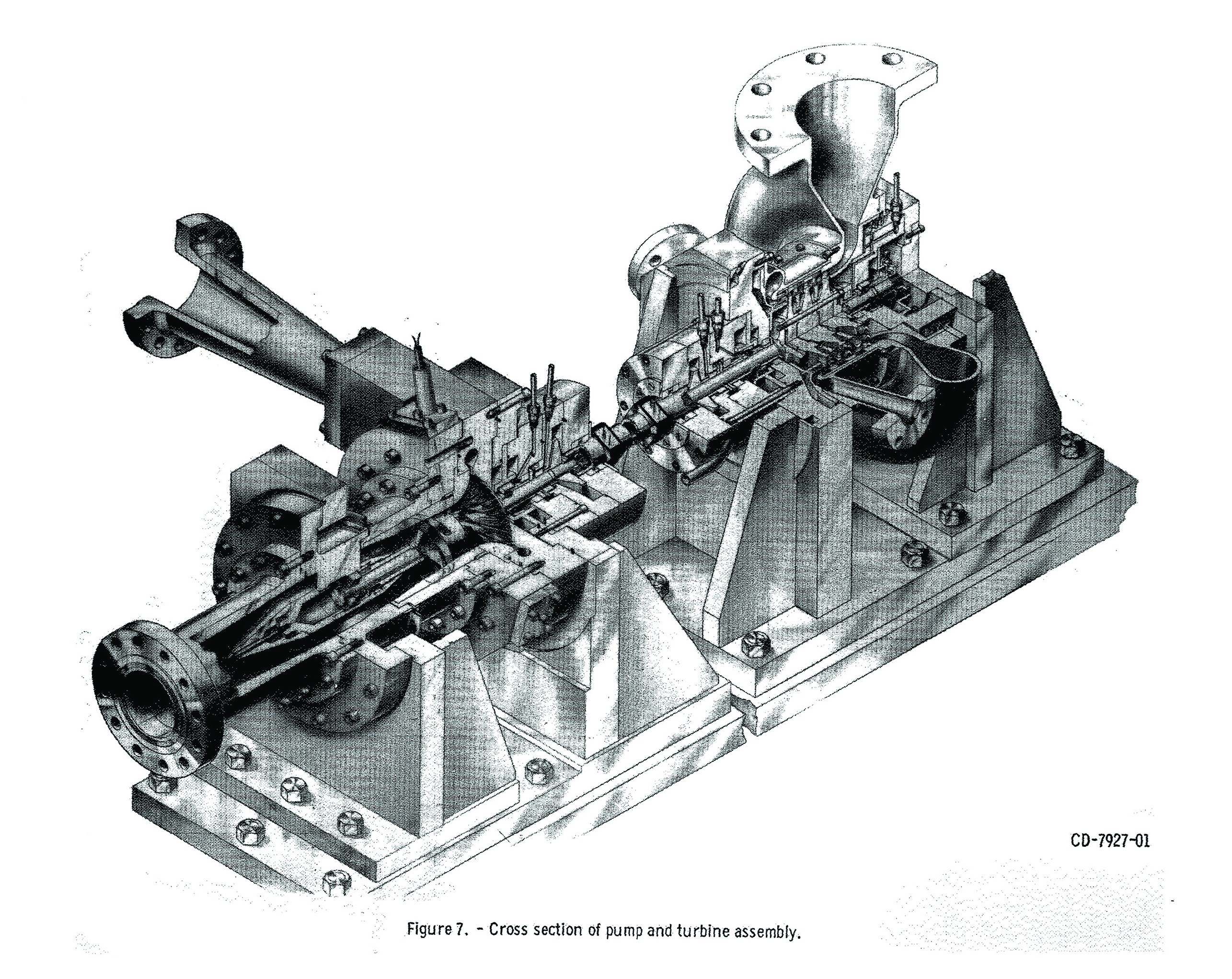
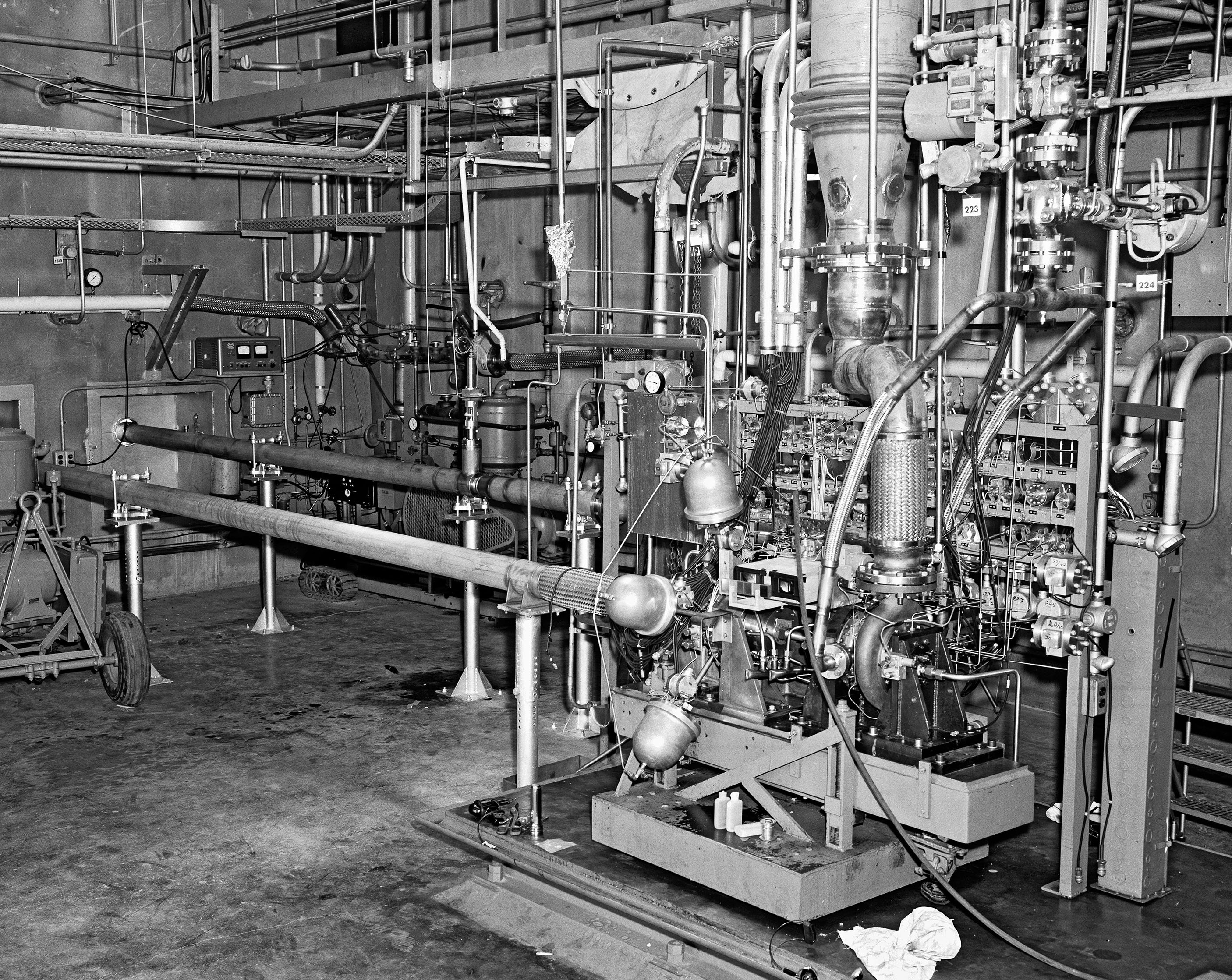
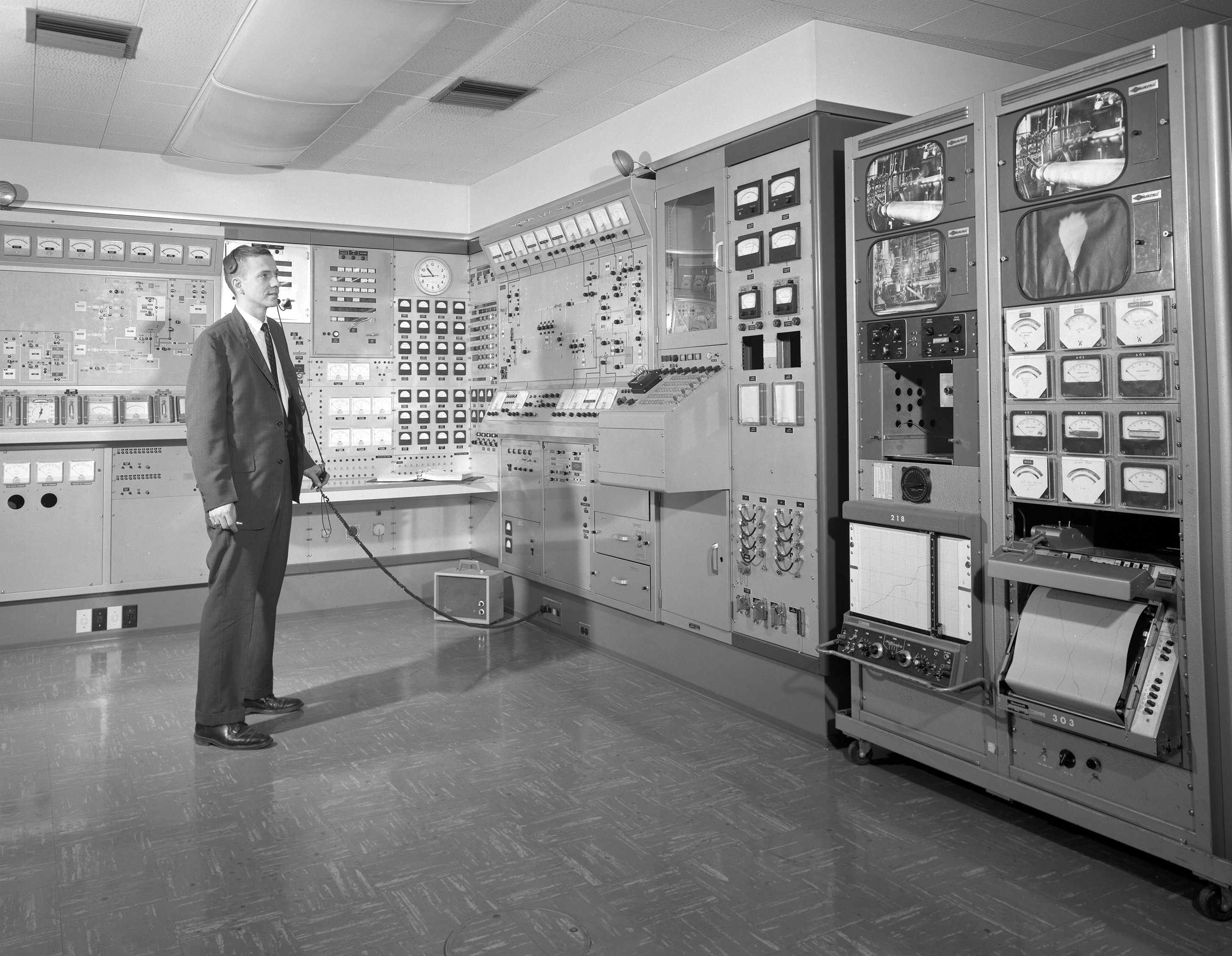
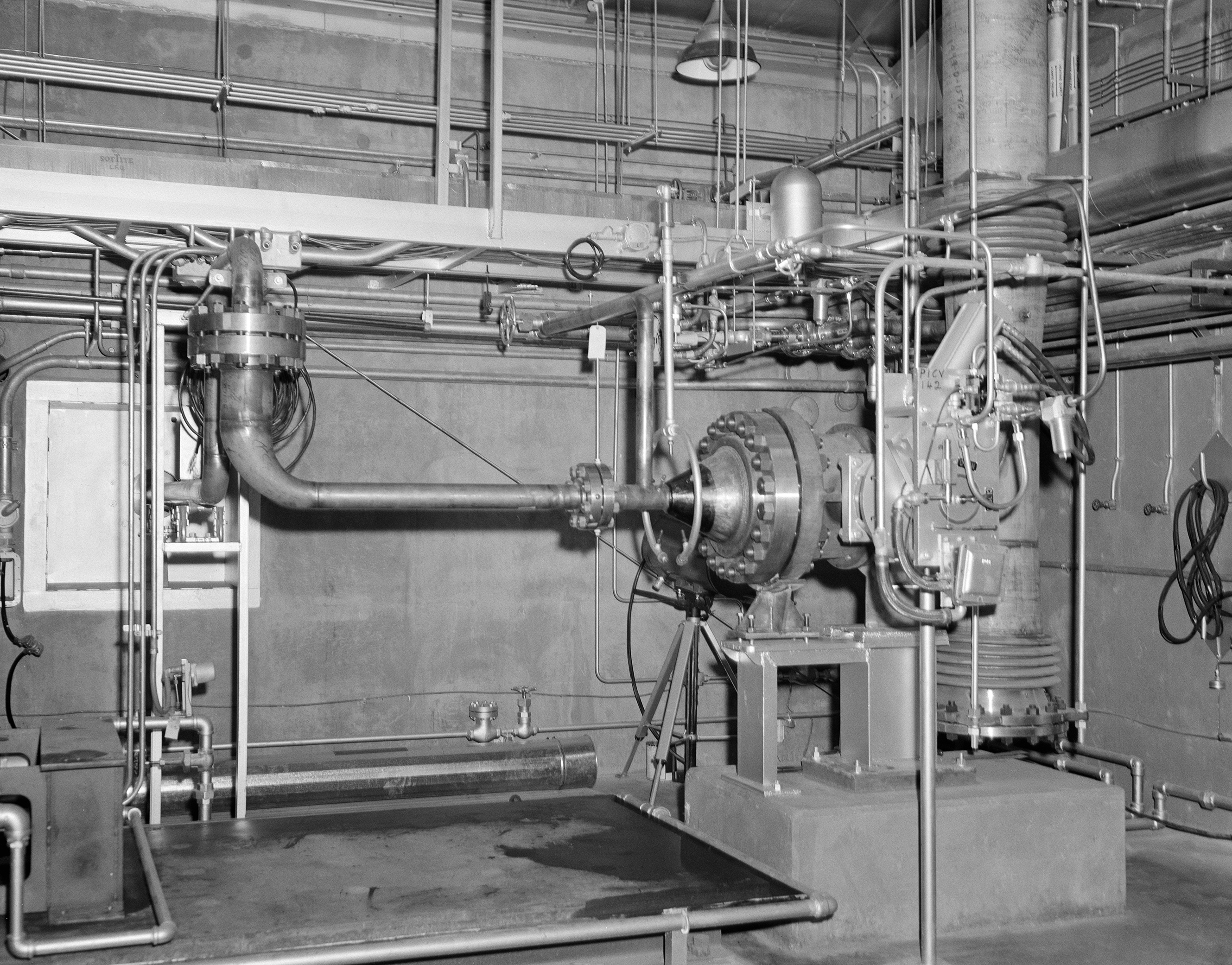
Operation: The staff installed the experimental turbopump on the drive shaft of either the hydrogen or oxygen test loop with an automatic thrust-balance compensator. The pump then transferred the fluid through a 3-in. stainless steel pipe from one 6000-gal Dewar to another. A gaseous-hydrogen-powered three-stage axial-flow turbine spun the drive shaft at up to 60,000 rpms to operate the pump. The hydrogen and oxygen loops could pump up to 20,000 and 1500 gal/min, respectively. To facilitate photographic analysis of the pump flow, designers gave the turbopump a transparent casing and put viewing ports in the test loop. The staff operated the tests and recorded the data from H Control about a quarter mile from the site.
Tests: Lewis researchers used A Site’s liquid hydrogen loop to study centrifugal and multistage axial-flow pump designs incorporating several different types of impellers and inducers. Researchers were only able to use the oxygen test loop, which suffered from many technical problems, for one series of tests. Its basic contribution was the problem-plagued testing of four NASA-designed impellers to support the M–1 engine program.
Hydrogen Test Loop
- 1961–62 Liquid-hydrogen centrifugal pump
- 1963–64 Impeller designs for liquid-hydrogen centrifugal pump
- 1965–66 Inducer blade loadings on a liquid-hydrogen centrifugal pump
- 1967–68 Four-stage axial-flow hydrogen pump
Oxygen Test Loop
- 1964 Oxygen turbopump for the M–1 engine
Documents
- A Site Description and Floor Plans
- A Site Status Reports (1963-68)
- Flow Range and Stability of Inducer-Impeller Combinations (1969)


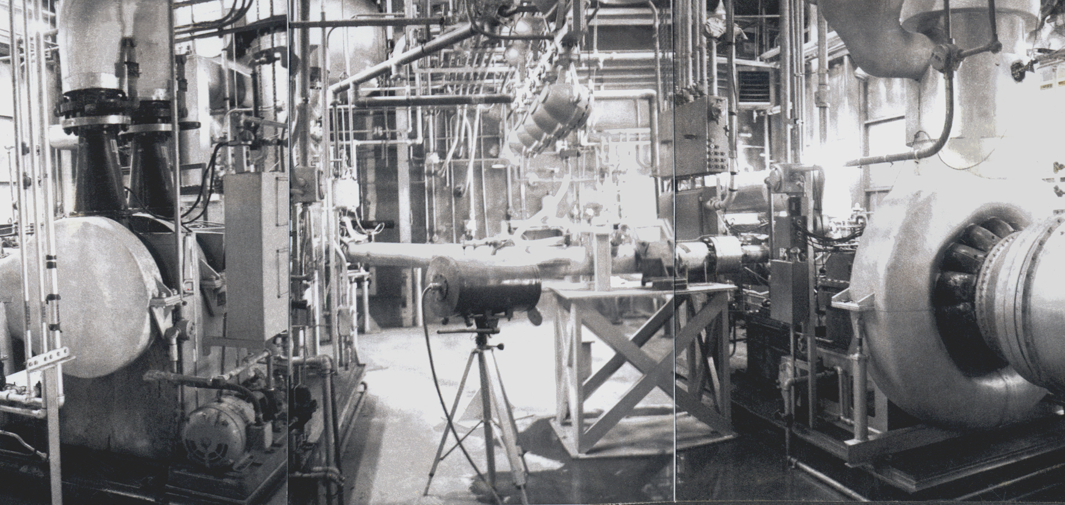
C-SITE – The Turbopump Facility
C Site was designed to study pump inducers that operate in boiling hydrogen and to test experimental turbopumps. C Site contained two test setups—a liquid-hydrogen turbopump and the Boiling Fluids Rig. Researchers used the former to investigate the matching of inducer and impeller stages for high-speed liquid-hydrogen turbopumps. The Boiling Fluids Rig allowed the analysis of experimental pumps at the near-boiling temperatures often found in hydrogen rocket systems.
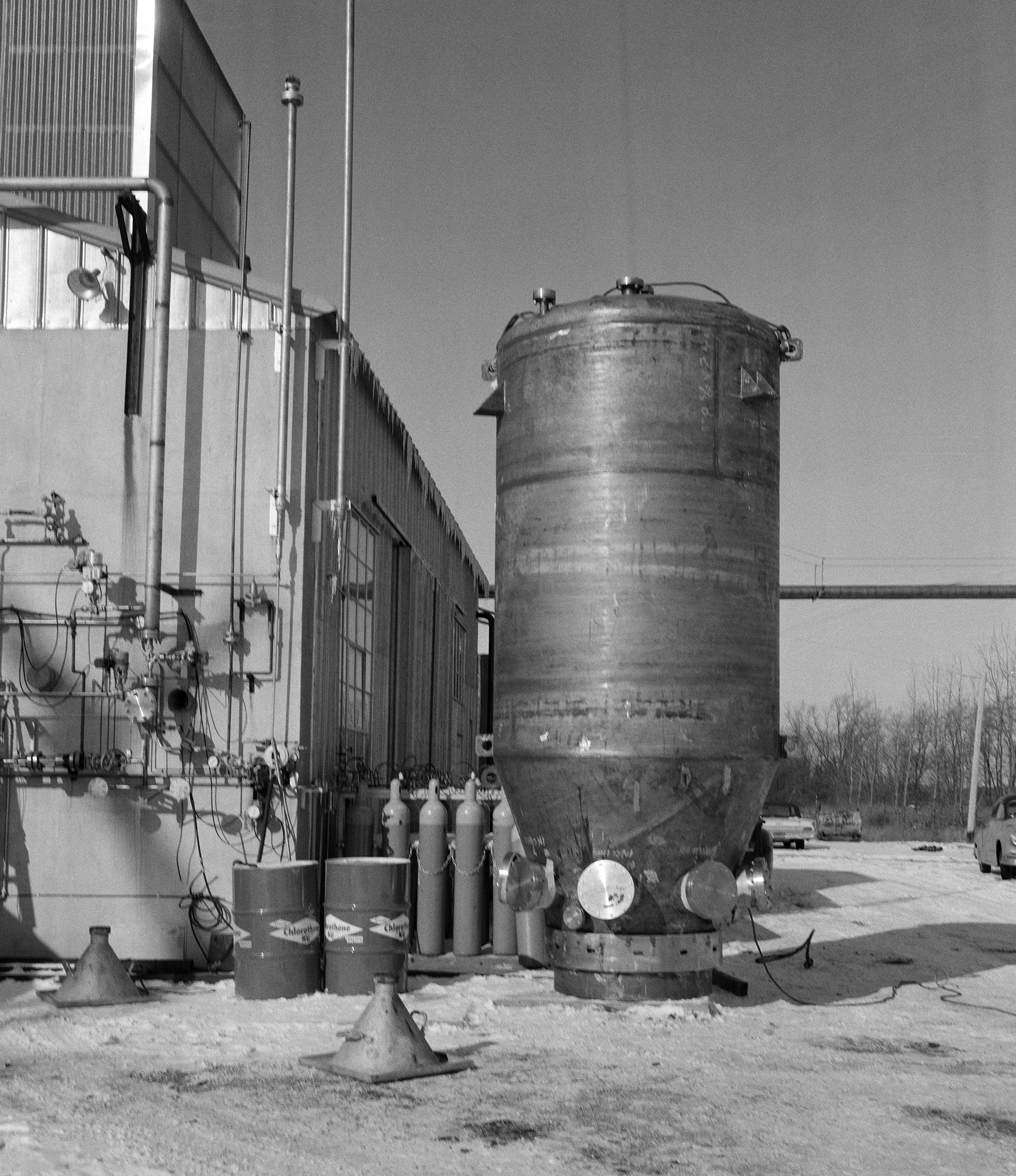
Physical Description: C Site was located on Ransom Road along the western portion of the Rocket Systems Area. The 2093-square foot test area was contained in a Butler Building, with the vertical tank for the Boiling Fluids Rig at the south end and the hydrogen pump loop on a steel plate at the north. The instrument, control, mechanical, and electrical rooms were in an annex off the north end. The portals and pumps used to transfer the propellants from portable 6000-gal trailers into the test Dewar were along the south wall. A vacuum pump room and two tank storage areas were in an extension of the western wall. A small pump house further east of the facility supplied high-pressure hydrogen gas to drive the turbine. C Site had a large shop building just to the east of the facility to prepare test articles.
Operation: The liquid-hydrogen turbopump at C Site worked similarly to the A Site loops. High-pressure hydrogen gas powered the turbine, which in turn spun the drive shaft connected to the experimental pump. The turbopump rapidly pumped the fluid from one 6000-gal tank to another. The rig accommodated run durations up to 5 min. Test engineers, which operated C Site remotely from the H Control Building, could independently adjust the fluid flow, speed, and pressure.
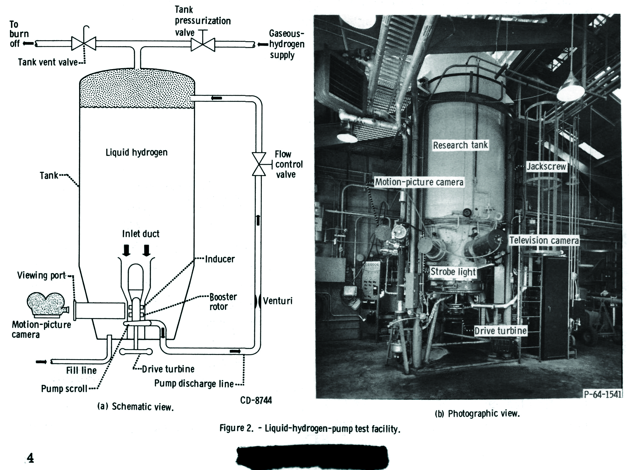
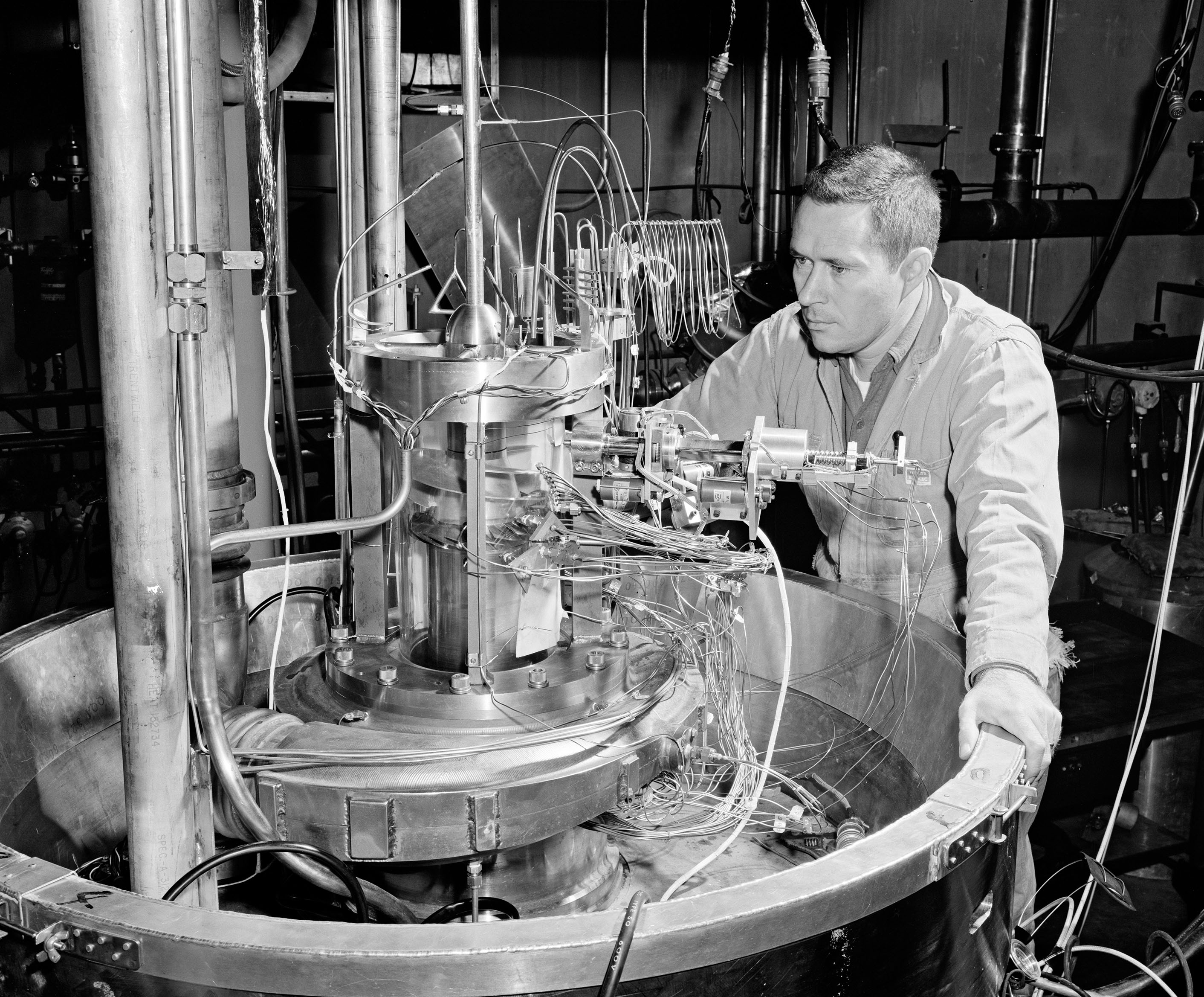
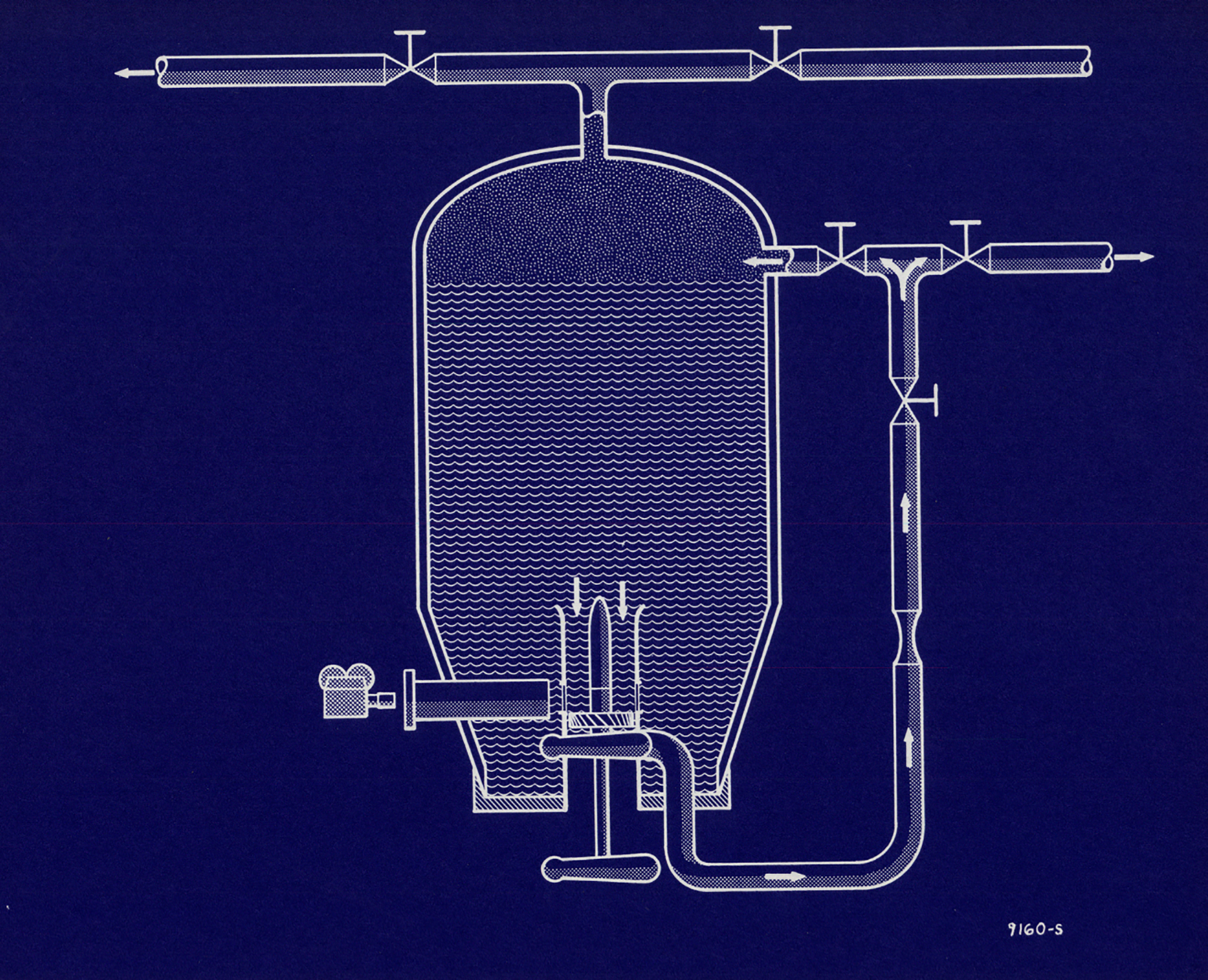
The Boiling Fluids Rig was a 2500-gal stainless-steel hydrogen tank with a transparent turbopump submerged at the bottom. The gaseous-hydrogen-powered drive turbine was located beneath the tank, whereas the pump’s inducer and impeller were in the tank. A shaft penetrating the bottom of the tank connected the pump and the turbine. The experimental pump recirculated the fluid out the bottom of the tank and into the top. The tank included viewing ports and a strobe lighting system that permitted the filming. Engineers added a cylindrical heater at the inlet to simulate temperatures in a nuclear engine.
Tests: Researchers used C Site’s Turbopump Rig to study inducers with angles of varying degrees as well as their performance in cavitation. Researchers used the Boiling Fluids Rig to study the rates of net positive suction head at the turbopump inlet when the liquid hydrogen was at higher temperatures and the effect of temperature, pressure, and flow rate on cavitation. Researchers also explored the use of slush hydrogen to reduce the size of the propellant tanks.
Boiling Fluids Rig
- 1962 Liquid-hydrogen pump
- 1963–64 Inducer performance in heat from nuclear rocket
- 1964 Inducer performance in slush hydrogen
- 1966 Minimal pressure required to pump hydrogen
- 1968 Comparison of different inducer blade shapes and angles
Hydrogen Turbopump Rig
- 1963–66 Impeller matching with centrifugal hydrogen pump
Documents
- C Site Description and Floor Plans
- C Site Status Reports (1963-68)
- Lewis Facilities to Study Cavitation in Pumps (1964)
- Performance of Line-Mounted 84° Inducer in Hydrogen (1967)
- Performance of Helical Inducer Operated in Hydrogen(1967)
- Change in Pressure Requirement in Low Temp Hydrogen (1968)
- Performance of 78° Helical Inducer in Hydrogen (1970)
- Effect of Leading Edge Thickness on Inducer Performance (1970)
D SITE – Controls and Turbine Test Facility
D-Site consisted two test rigs for testing multistage turbines that powered turbopumps on chemical and nuclear rocket engine systems. The staff unsuccessfully struggled for several years to get the facility to operate properly.
Physical Description: D Site is located at the intersection of Ransom and Fox roads at the northwest corner of the Rocket Systems Area. The test equipment was contained in a 1,511 square foot rectangular Butler Building with mechanical, control, and instrument rooms added along the east end. Liquid-oxygen and liquid-hydrogen tank pits with their respective gas generator rooms were located outside the north wall. The main test area included a large office and electronic shop and two overhead cranes (5 ton and 1.5 ton). A shop building and a small pump house were located to the southeast, and a hydrogen burnoff line extended from the facility to the north.
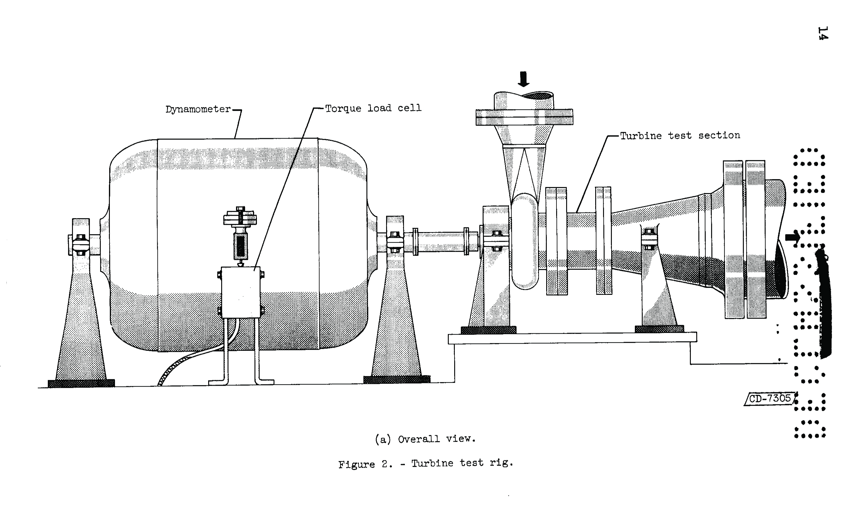
Operation: The staff was able to install two 15,000-hp, 60,000-rpm turbines simultaneously at D Site. Each rig included its own gas generators, high-speed gearbox, and eddy-current dynamometers. The gas generators converted the liquid propellants into gas to operate the turbines. The dynamometers, also mounted to the bedplate, acted like brakes on the turbine and measured the turbine’s output. The staff operated D Site from the H Control Building.
Testing: Researchers installed an eight-stage turbine in one of D Site’s test rigs and a three-stage turbine in the other. The turbines were intended for a 100,000-lb-thrust hydrogen-oxygen engine and a nuclear rocket engine. Delays and equipment problems prevented successful testing for several years. Lewis Research Center decided to permanently shut down the two rigs in 1964 and 1965.
Documents

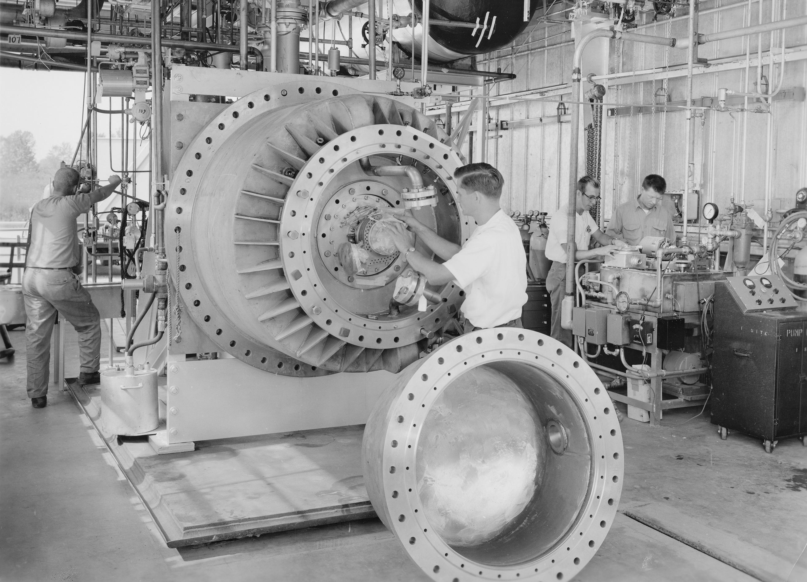
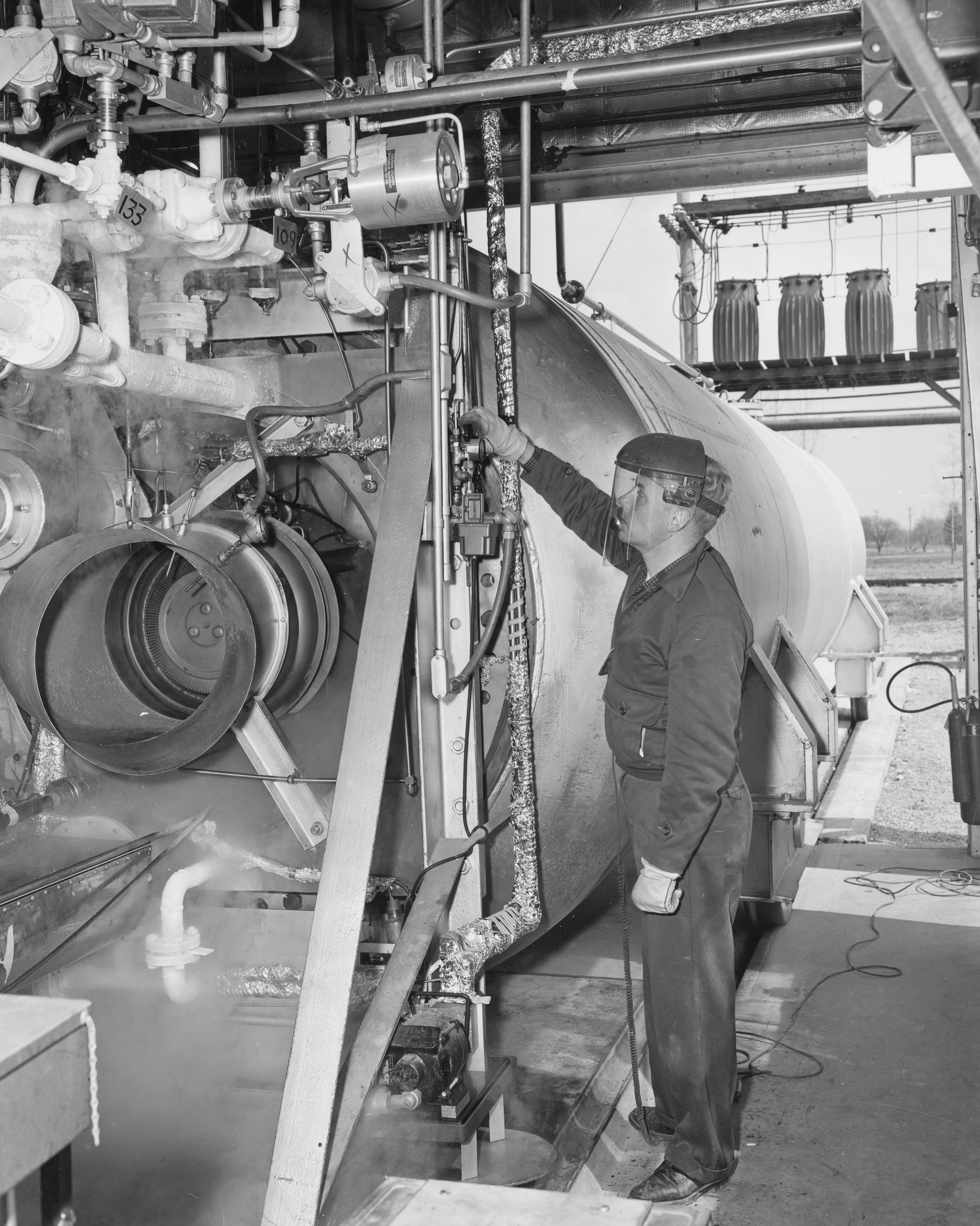
I SITE – The Fluorine Pump Facility
I Site was designed the test liquid-fluorine turbopumps that operate at 20,000 rpm and produce flow rates up to 50 lb/sec.
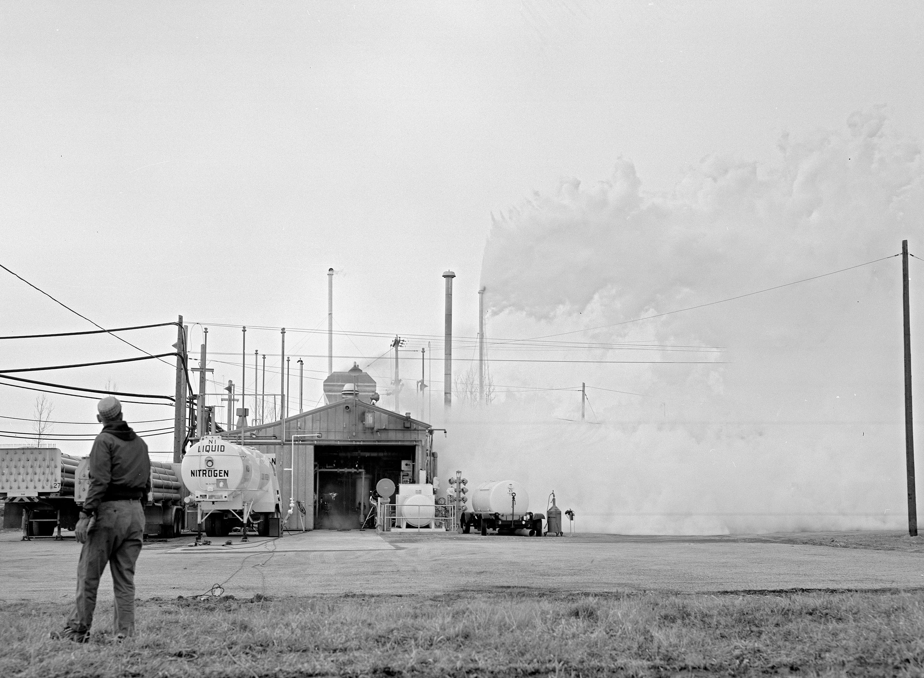
Physical Description: I Site was located on Taylor Road near the center of the Rocket Systems Area. The main structure was a rectangular Butler Building with an open interior in which the test loop was set up. The actual pump test section was in a 855-square foot annex along the southeastern wall that opened to the exterior. The I Site setup was a closed-loop system in which liquid fluorine was circulated by the research turbopump. This pump was enclosed inside a 9500-lb stainless steel containment vault and wrapped in what was called a “burn wire,” which automatically closed emergency valves in the case of a fire. Trailer tankers supplied the facility through ports in the northeastern wall. Small instrument, control, and mechanical equipment rooms lined the northwest wall of the building. A large shop building was located to the east of the primary I Site structure.
Operation: The staff passified the system before the test with a gaseous-fluorine system. The liquid fluorine was stored in a 600-gal run tank that was pressurized with helium. A heat exchanger maintained the fluid temperature to extend run times. The operator, located 1200 ft away in the H Control Building, opened the valves to allow the fluorine to flow into the loop. Then the experimental pump circulated the fluorine through the loop and back into the Dewar. The pump, powered by an airbreathing turbine, initially operated at lower speeds then increased until it reached normal operating speeds.
Tests: Researchers established a test program at I Site to obtain the performance characteristics of NASA-designed fluorine pumps during cavitation, study the effect of cavitation on the fluoride surface coating, and analyze rotating shaft seal designs. Pratt & Whitney researchers also used I Site to determine if fluorine could be used in their RL–10 engines and to explore the use of a methane-fluorine/oxygen (FLOX) propellant in the engine. 1962–64 Lewis liquid-fluorine centrifugal turbopumps 1963–65 Pratt & Whitney RL–10 fluorine turbopumps 1964 Fluorine turbopump seals 1966 Pratt & Whitney FLOX/methane turbopump
Documents
- I Site Description and Floor Plans
- I Site Status Reports (1963-67)
- Plum Brook Today article (1960)
- Operation of Liquid Fluorine Pump in Cavitating Flow (1968)
Images: