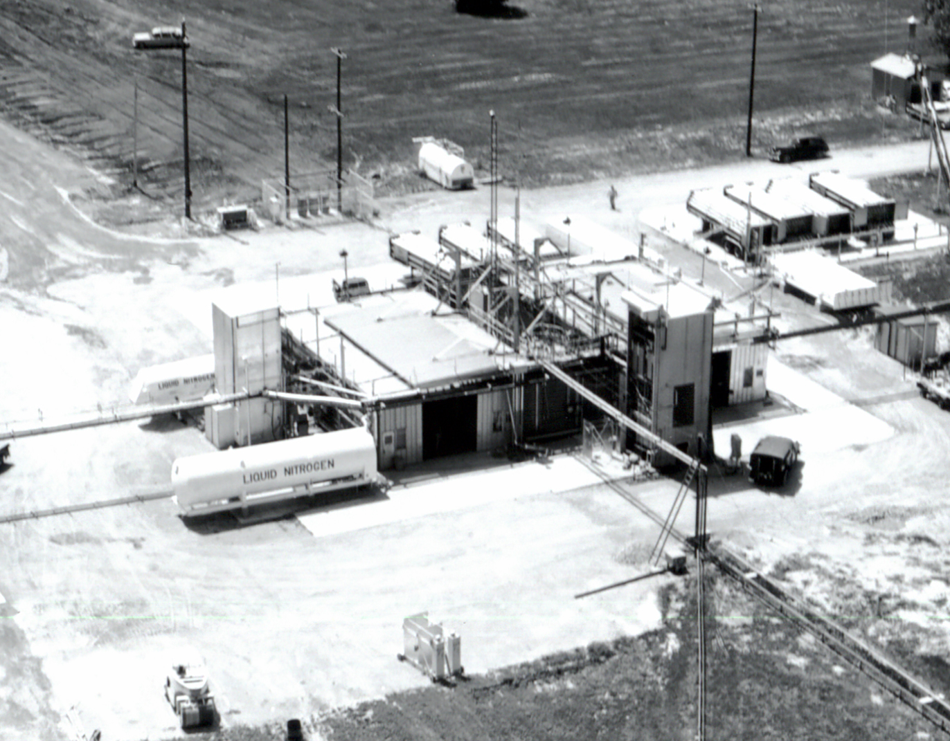
J Site – Rockets System Test Site
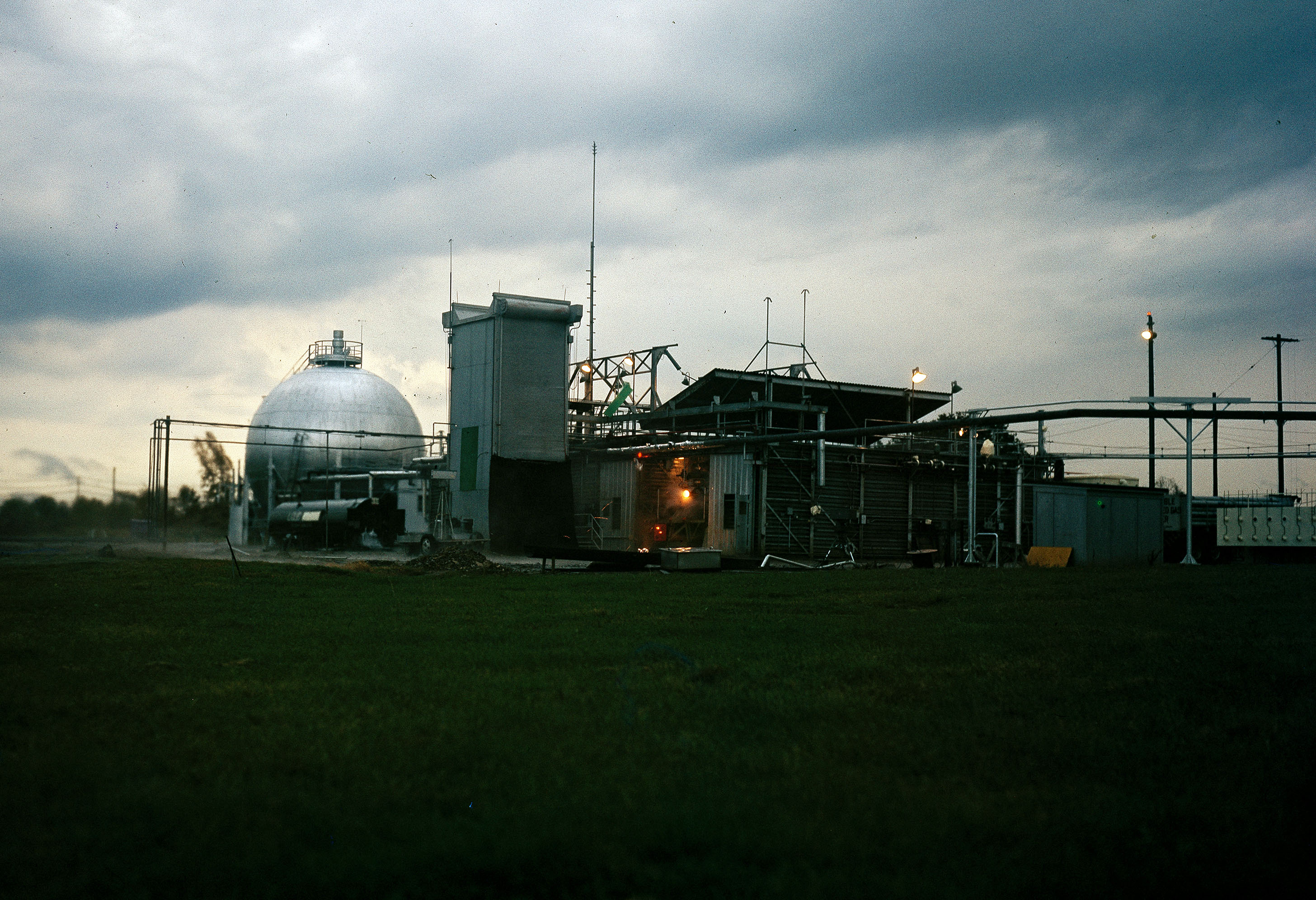
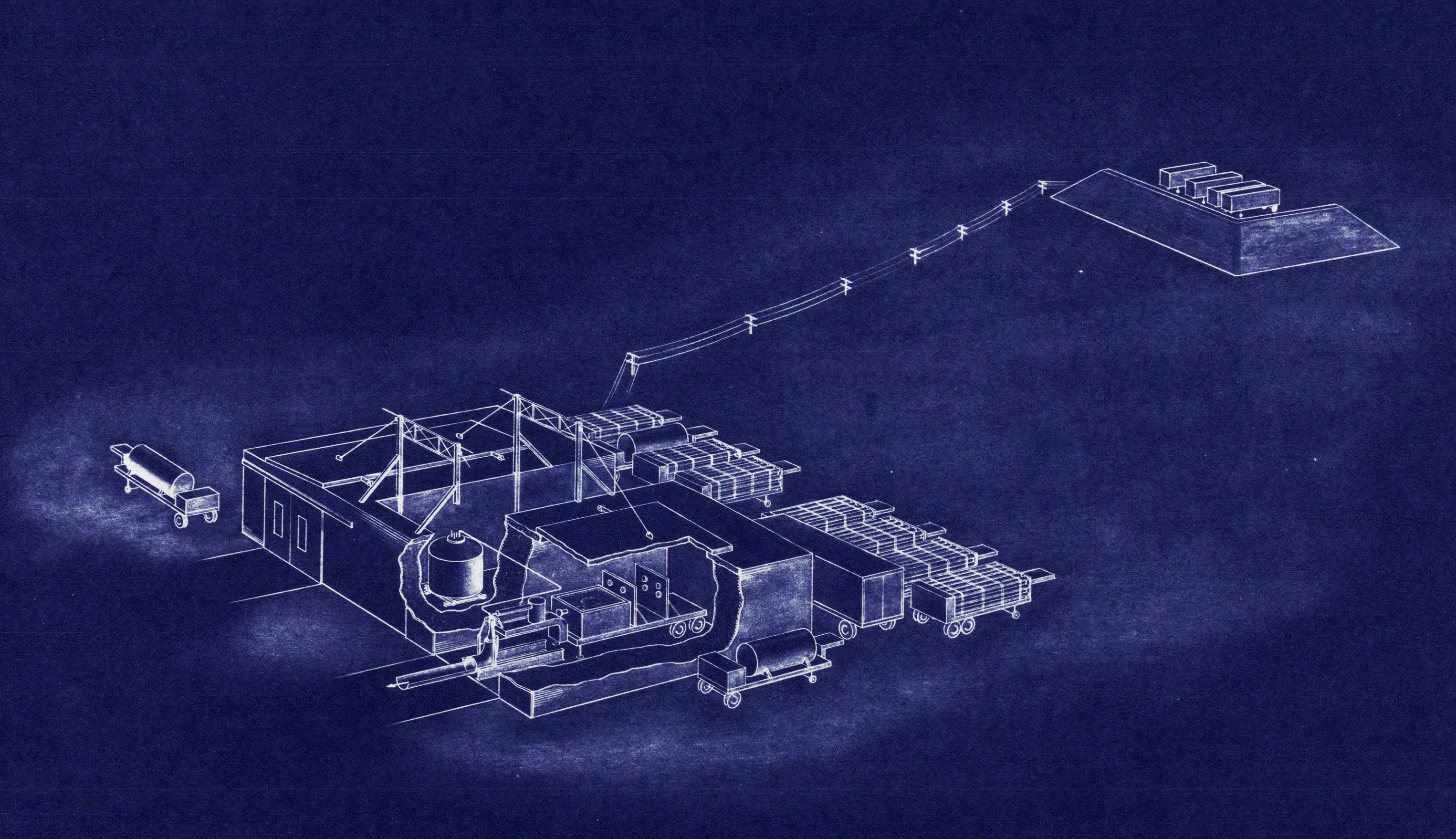
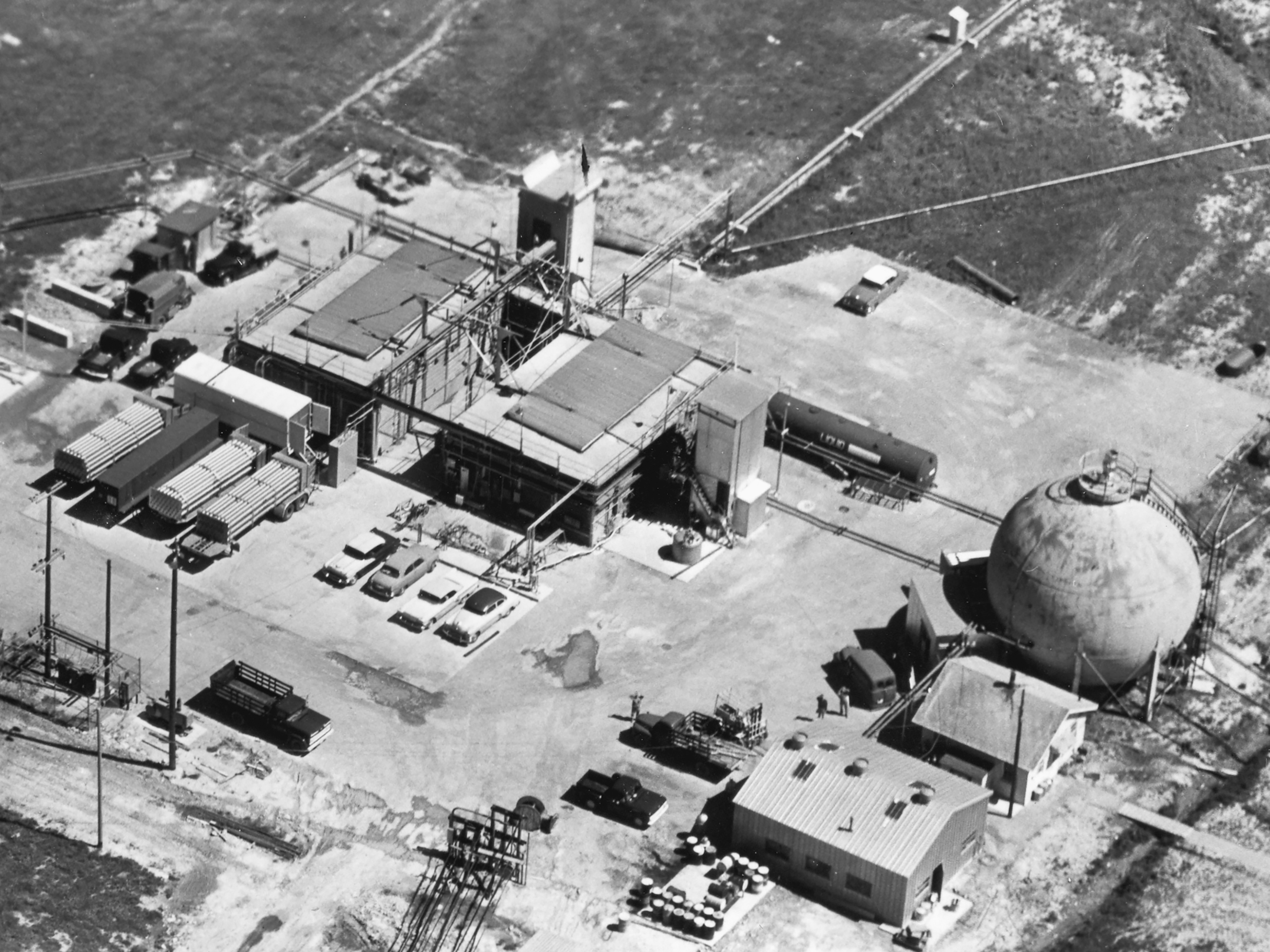
J Site, which was located on Taylor Road near the center of the Rocket Systems Area, consisted of five different test facilities used to investigate issues regarding rocket combustion, propellant storage, heat transfer, and fluorine handling. The main structure was a C-shaped building that housed two test rigs with an external liquid-hydrogen tank between them. The vertical test stands were located just off the north and east sides of the building. A large round tank was nearby further east. The main control room for the site was located in portable trailers behind earthen mounds to the southwest.
J-1
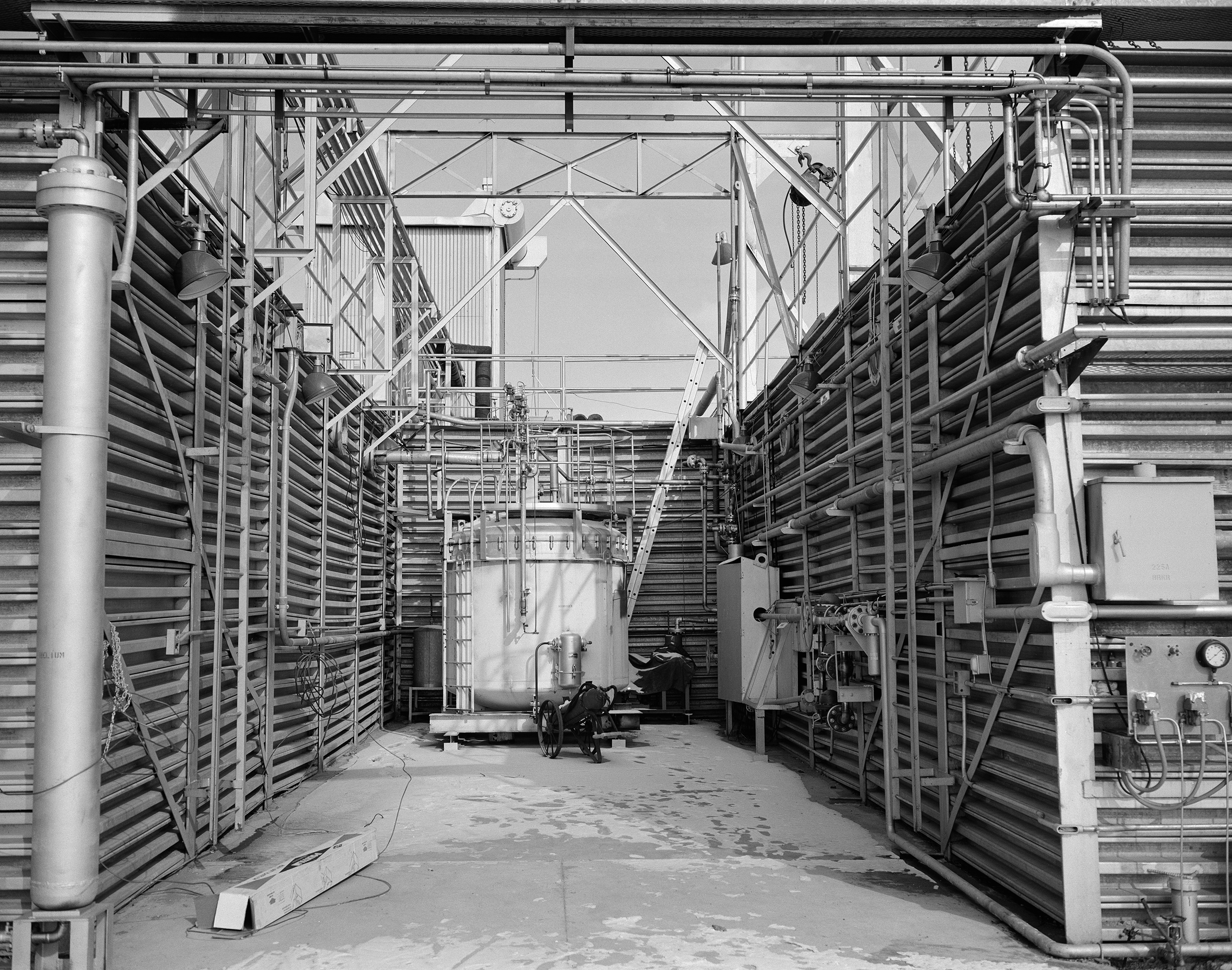
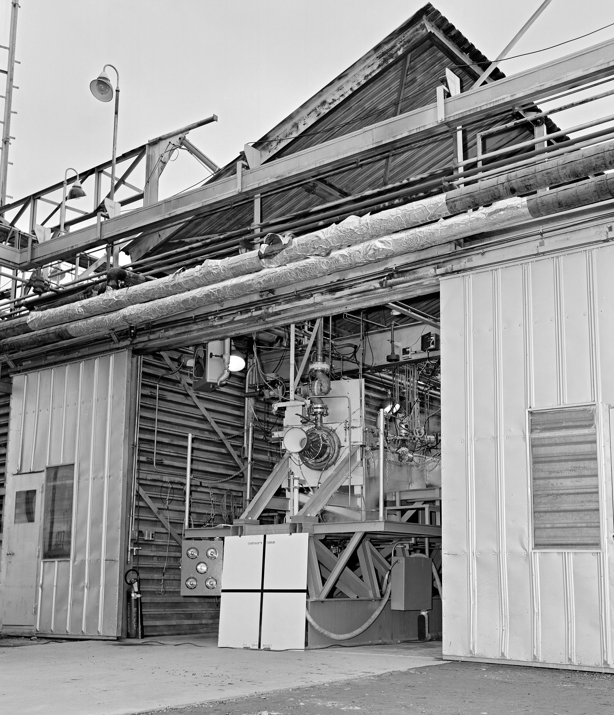
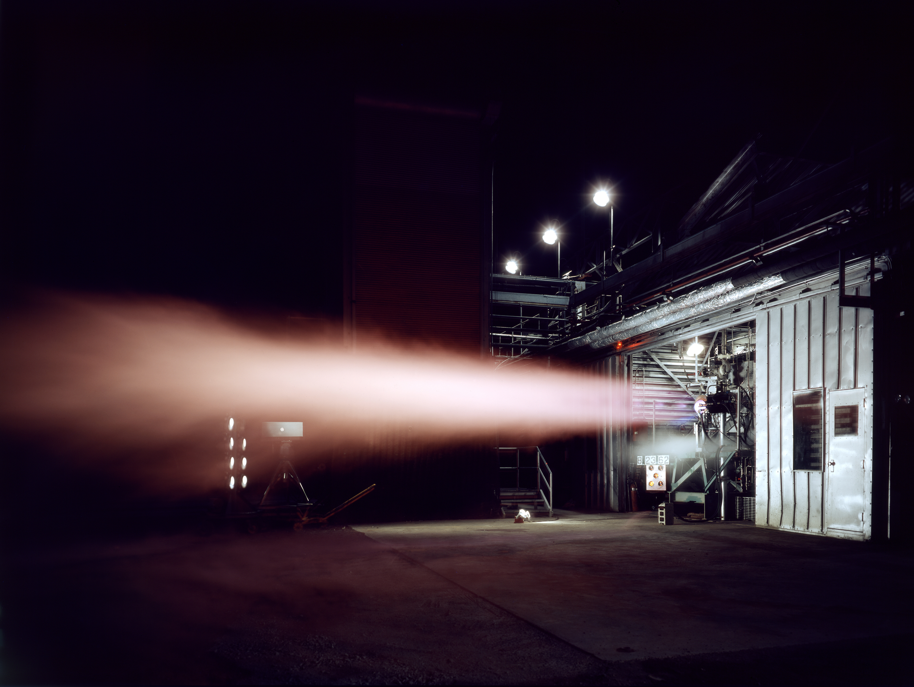
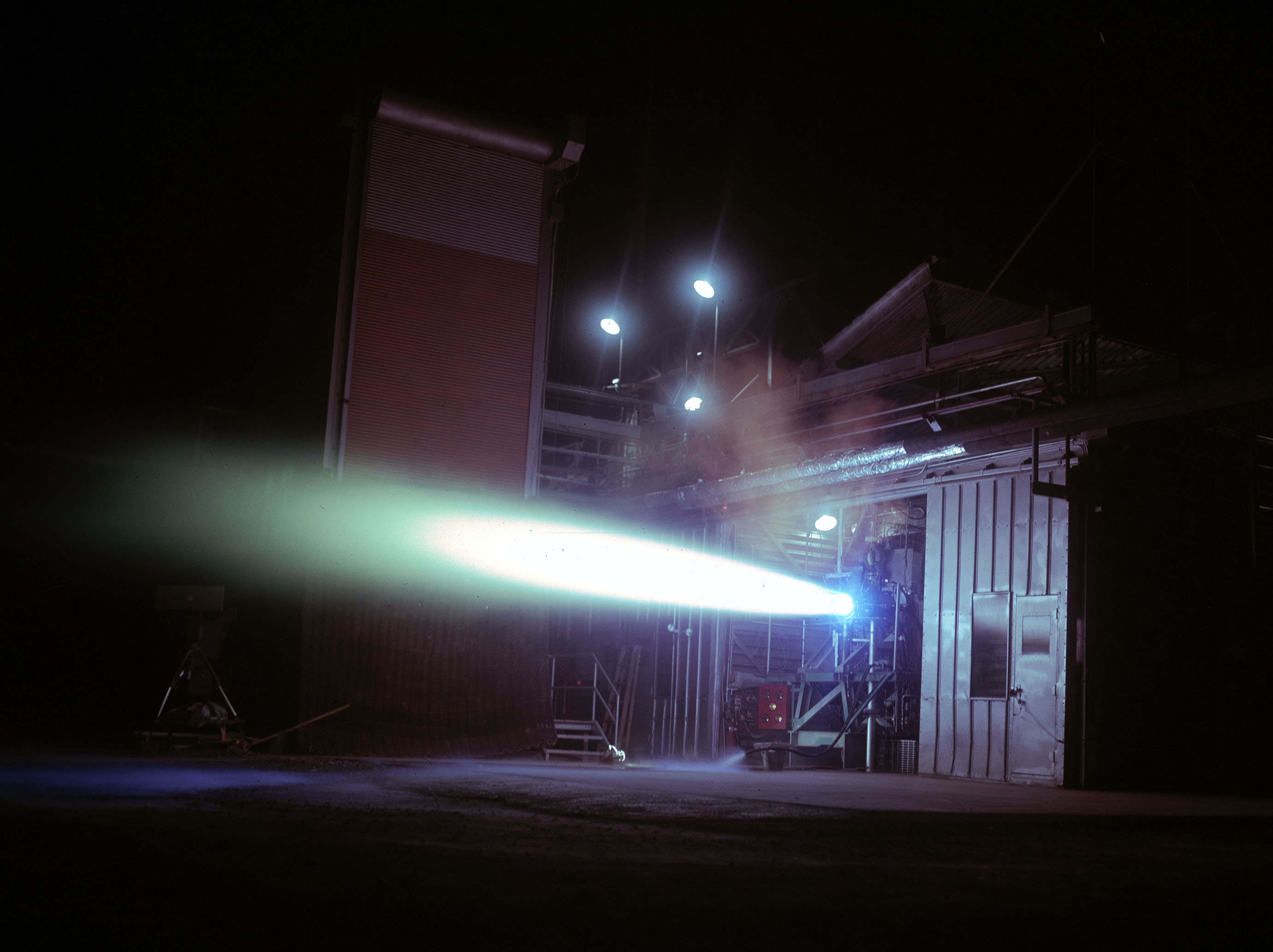
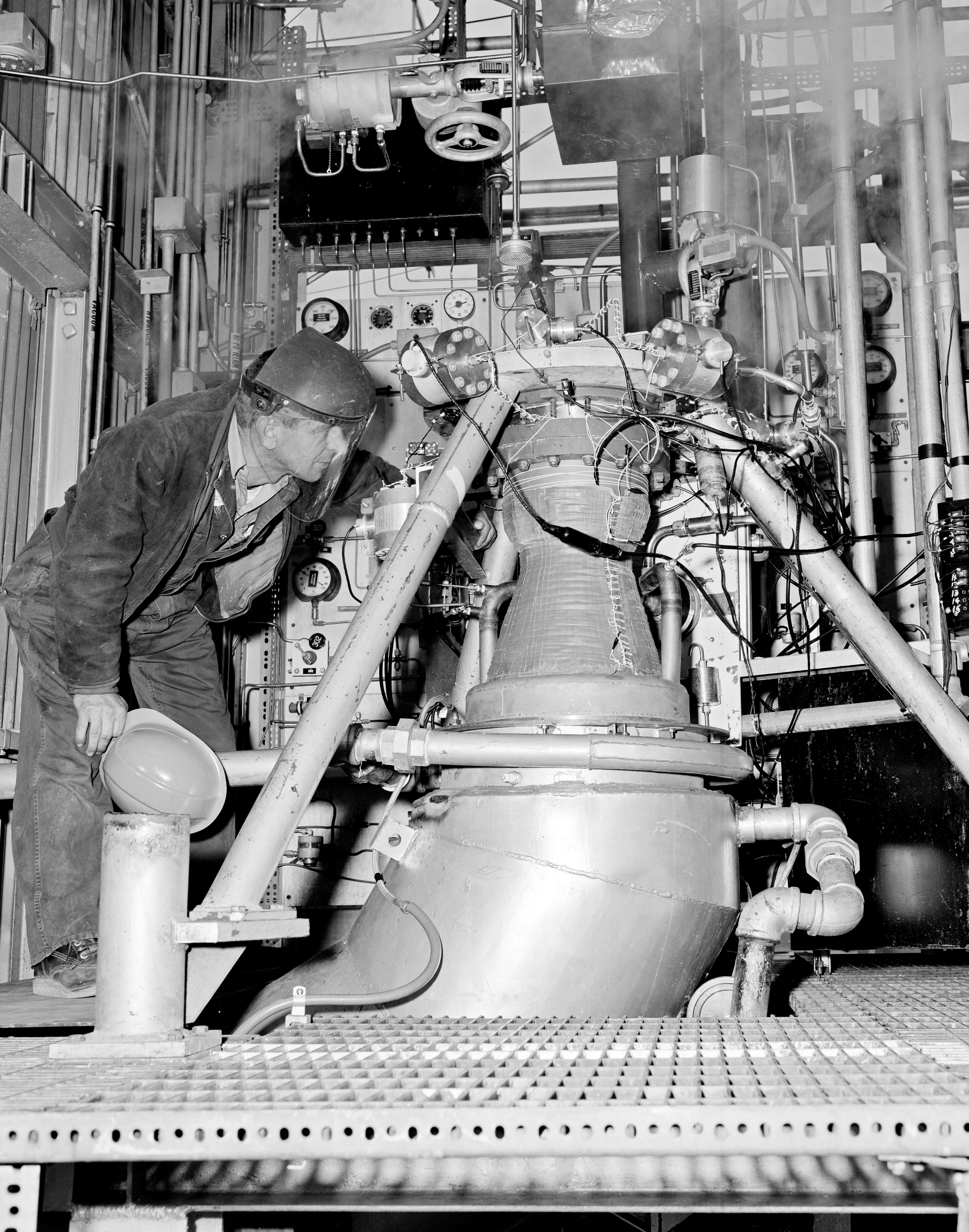
Physical Description: J–1 was a horizontal rocket test stand located in the northwest half of J Site’s main structure. The structure’s walls consisted of earth encased in metal siding. Mobile propellant tanks fed the facility from the south wall, and there was a permanent liquid-hydrogen tank just outside the east wall. The J–1 rig was elevated approximately 5 ft above the ground and fired horizontally through a large door in the north wall.
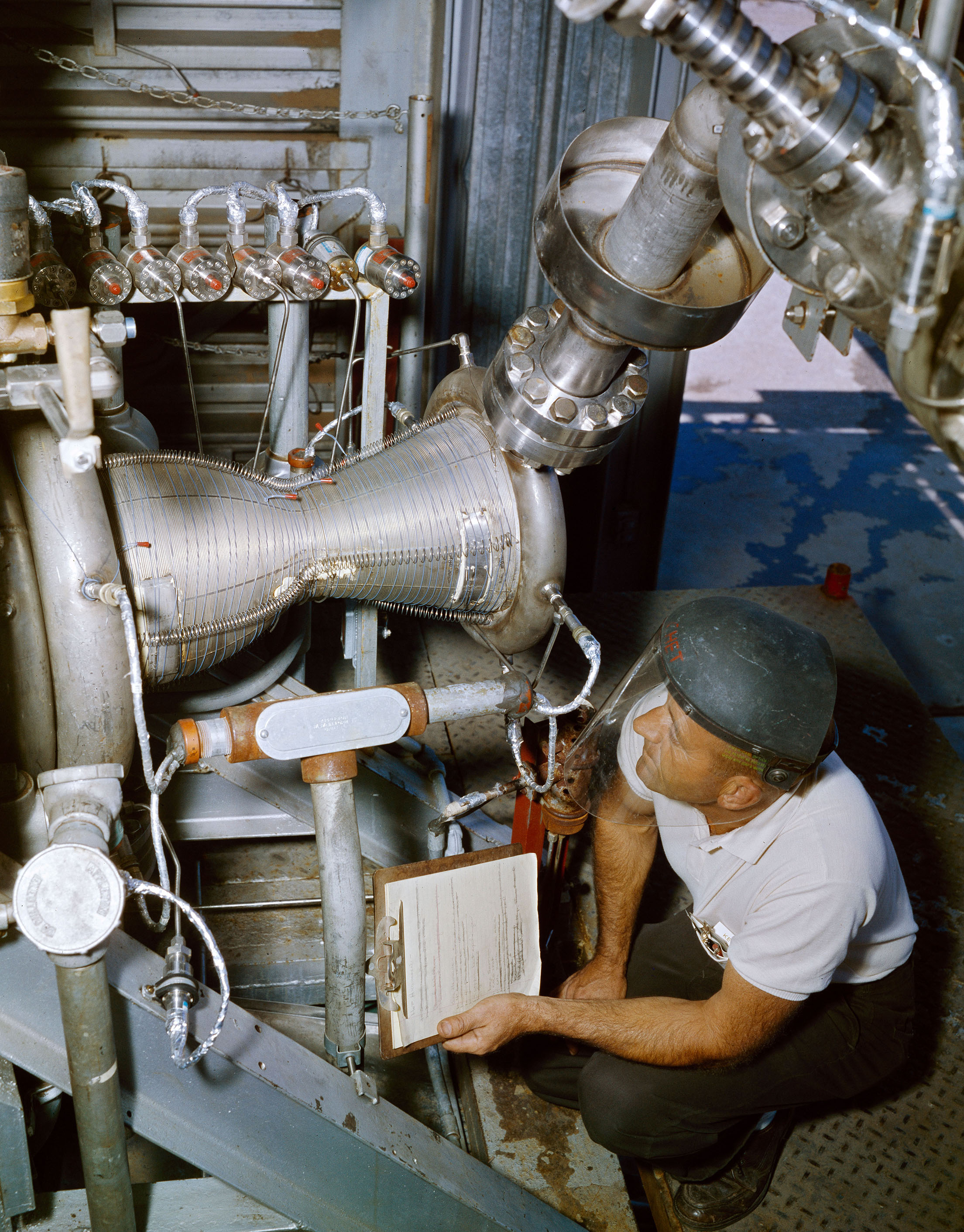
Operation: The staff installed the experimental engine and opened the building’s sliding doors. The operators, located in the J Control trailers, adjusted the propellant and coolant pressure to the desired levels. They then initiated the test, which automatically opened the supply valves and fired the engine. The runs typically lasted only a few seconds. The coolant flow was sent to a burnoff system instead of to the injector so that it did not influence the nozzle’s heat transfer data.
Tests: Researchers used J–1 for a multiyear study of the heat transfer to and from liquid hydrogen in regeneratively cooled nuclear rocket nozzles and basic hydrogen-oxygen engine tests.
- 1961–62 Gaseous-hydrogen/liquid-oxygen rocket engine
- 1963 Hydrogen burnoff tests for the Hydrogen Heat Transfer Facility (HHTF) design
- 1962–63 Copper hydrogen-oxygen engine for nuclear rocket heat transfer
- 1964–68 Injectors for steel hydrogen-oxygen engines
- 1964–68 Regeneratively cooled liquid-hydrogen engines
Documents
- J Site Description and Floor Plans
- J1 Status Reports (1961-68)
- Investigation of Hot-Gas-Side Heat Transfer(1965)
- Hot-Gas-Side Heat Transfer in Hydrogen-Oxygen Rocket(1971)
- Hot-Gas-Side Heat Transfer With/Without Film Cooling(1972)
- Coolant-Side Heat Transfer Rates for Rocket (1973)


J-2
J–2 was a rocket test stand designed to study throttling and heat transfer in rocket engines that used high-energy propellants such as liquid hydrogen and liquid fluorine.
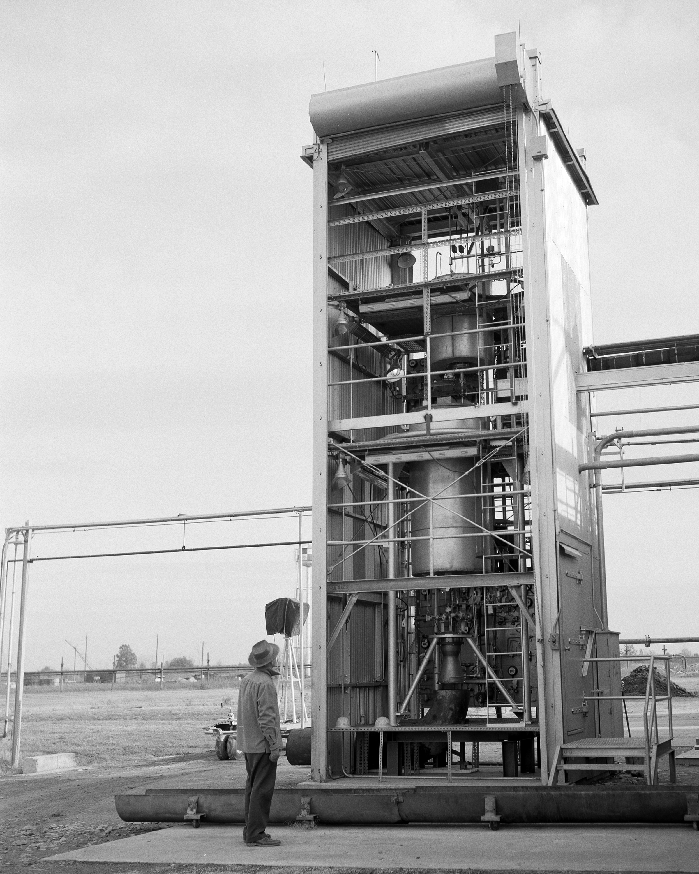
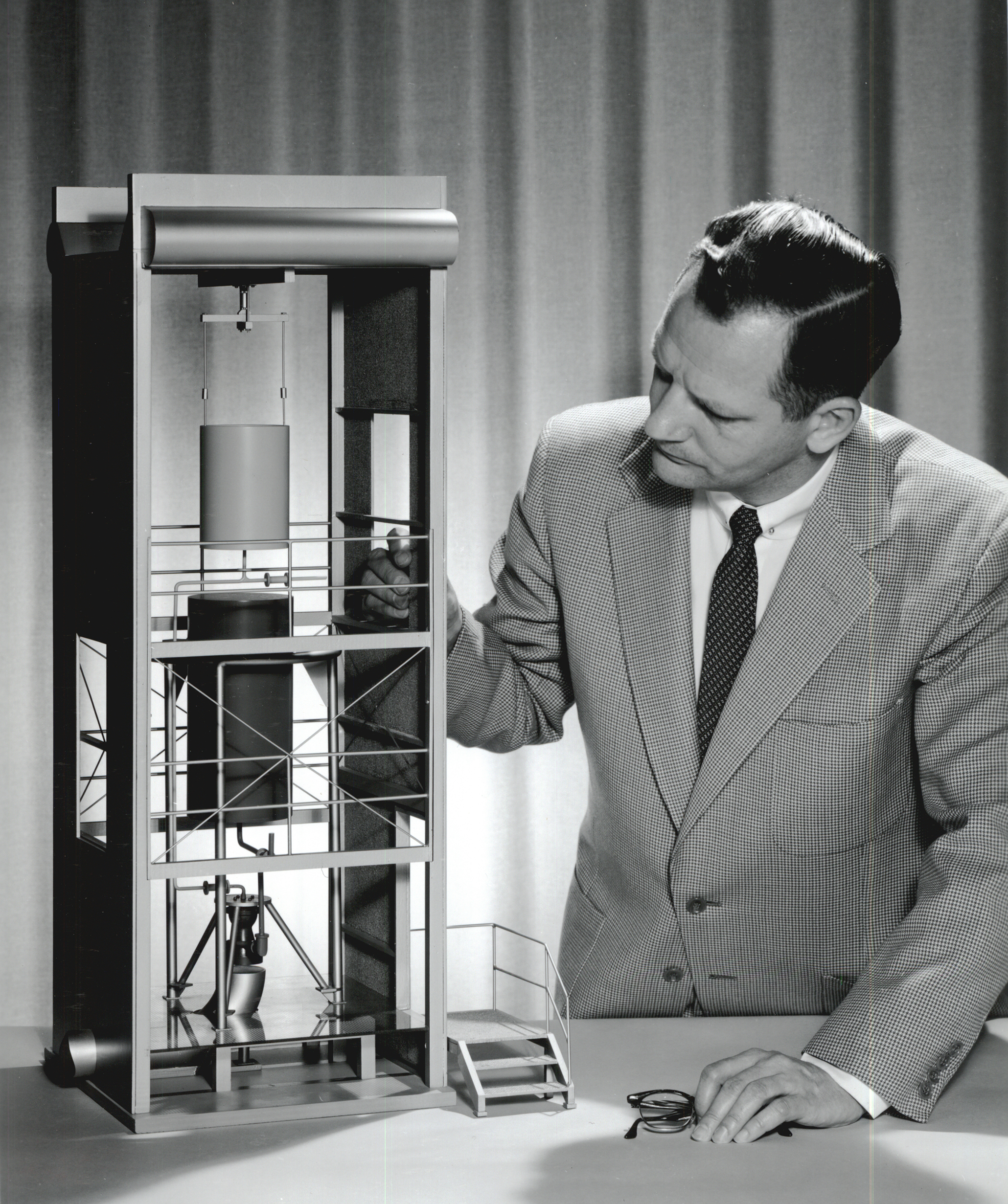
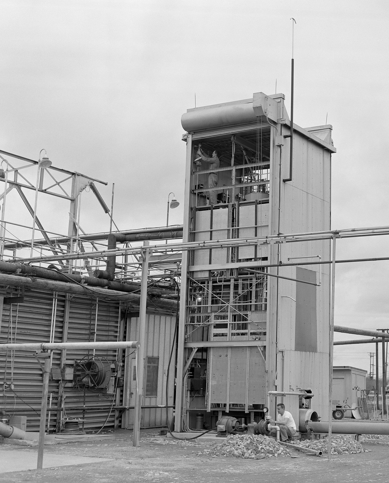
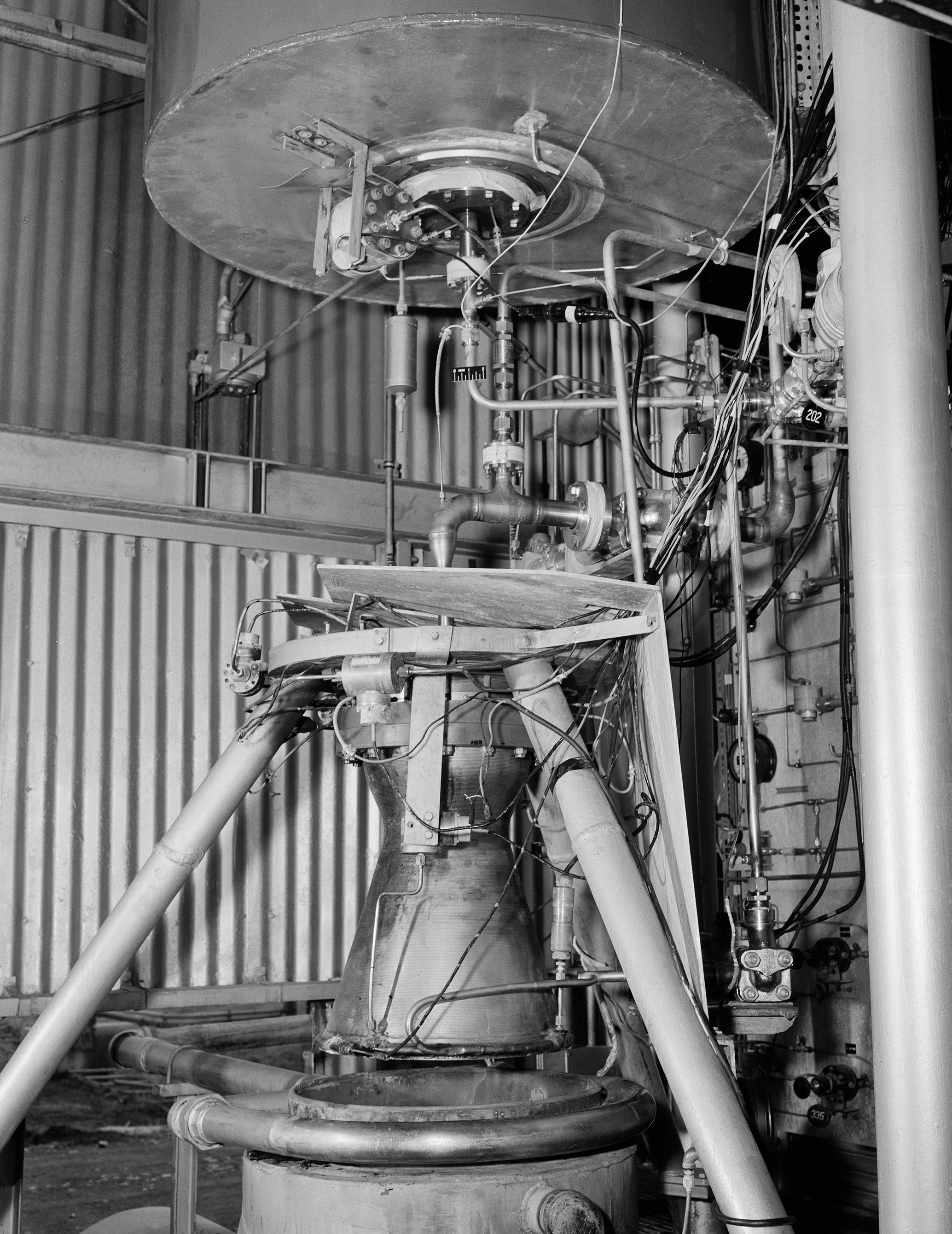
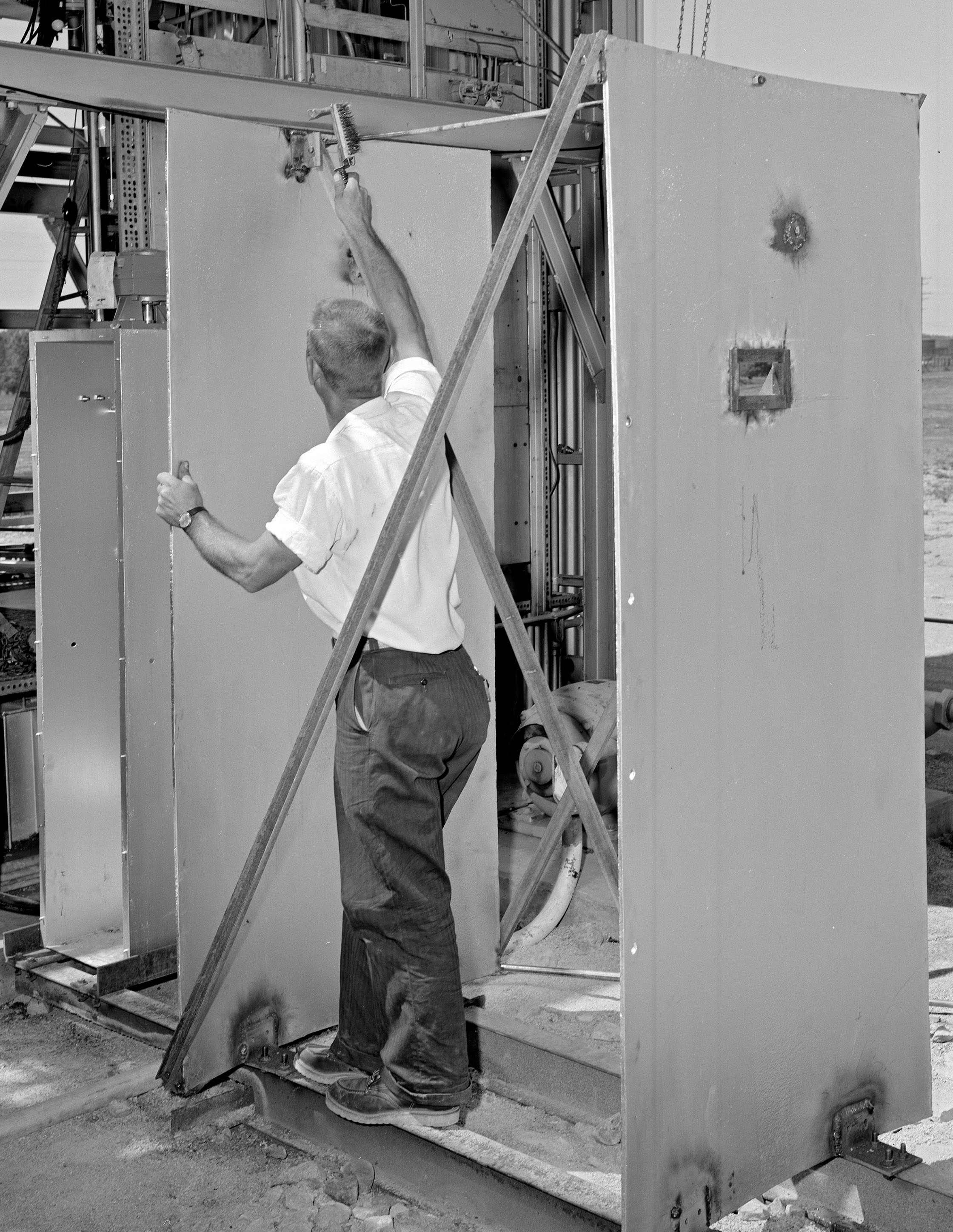
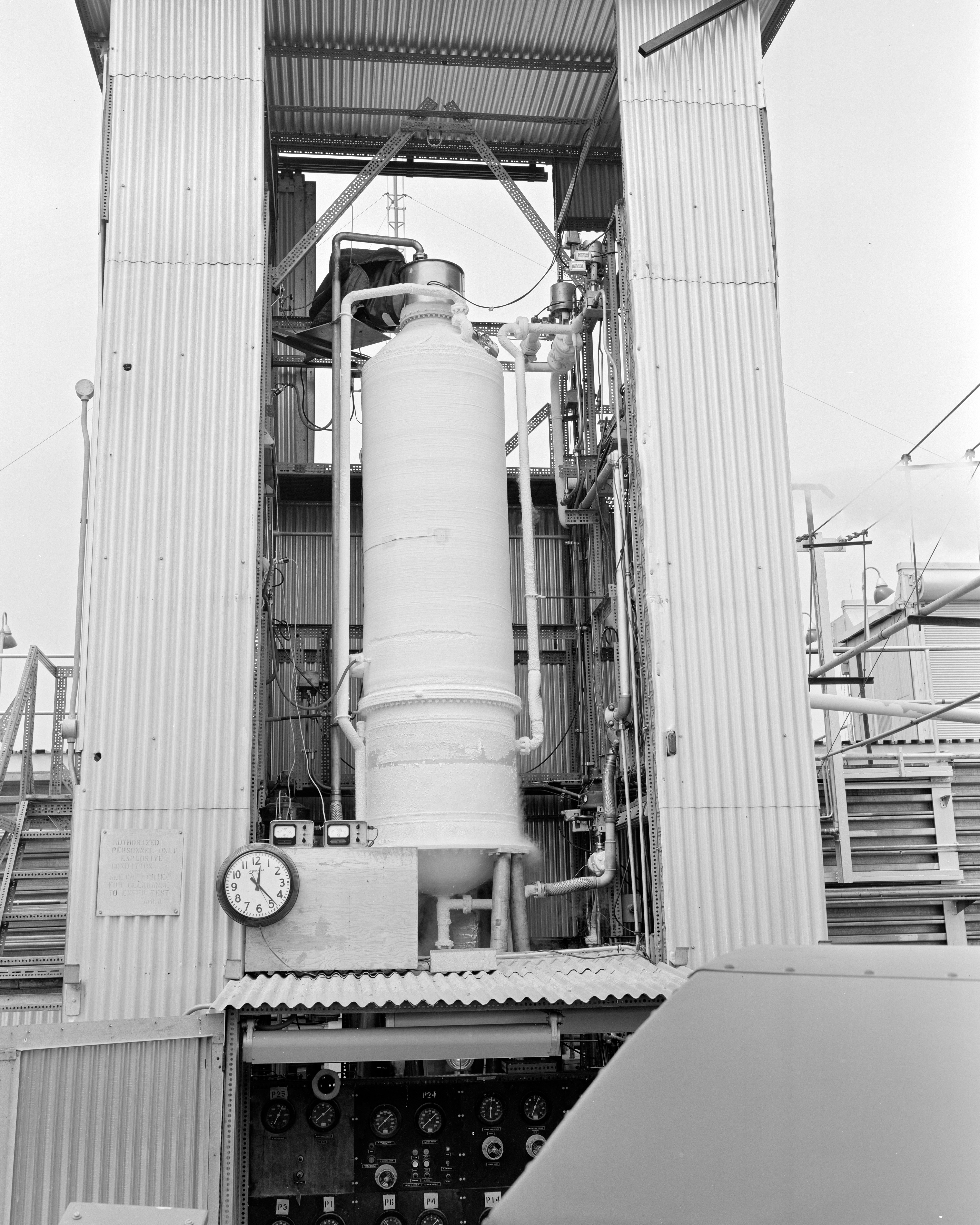
Physical Description: The J–2 vertical stand was located outside of the northeastern wall of the main J Site structure. The approximately 25-ft-high stand allowed the oxidizer tank to be mounted above the fuel tank for a more realistic simulation. The tower had rollup doors on either side to provide ventilation during the tests. The engine fired downward into a U-shaped duct, which directed the exhaust horizontally out into the atmosphere.
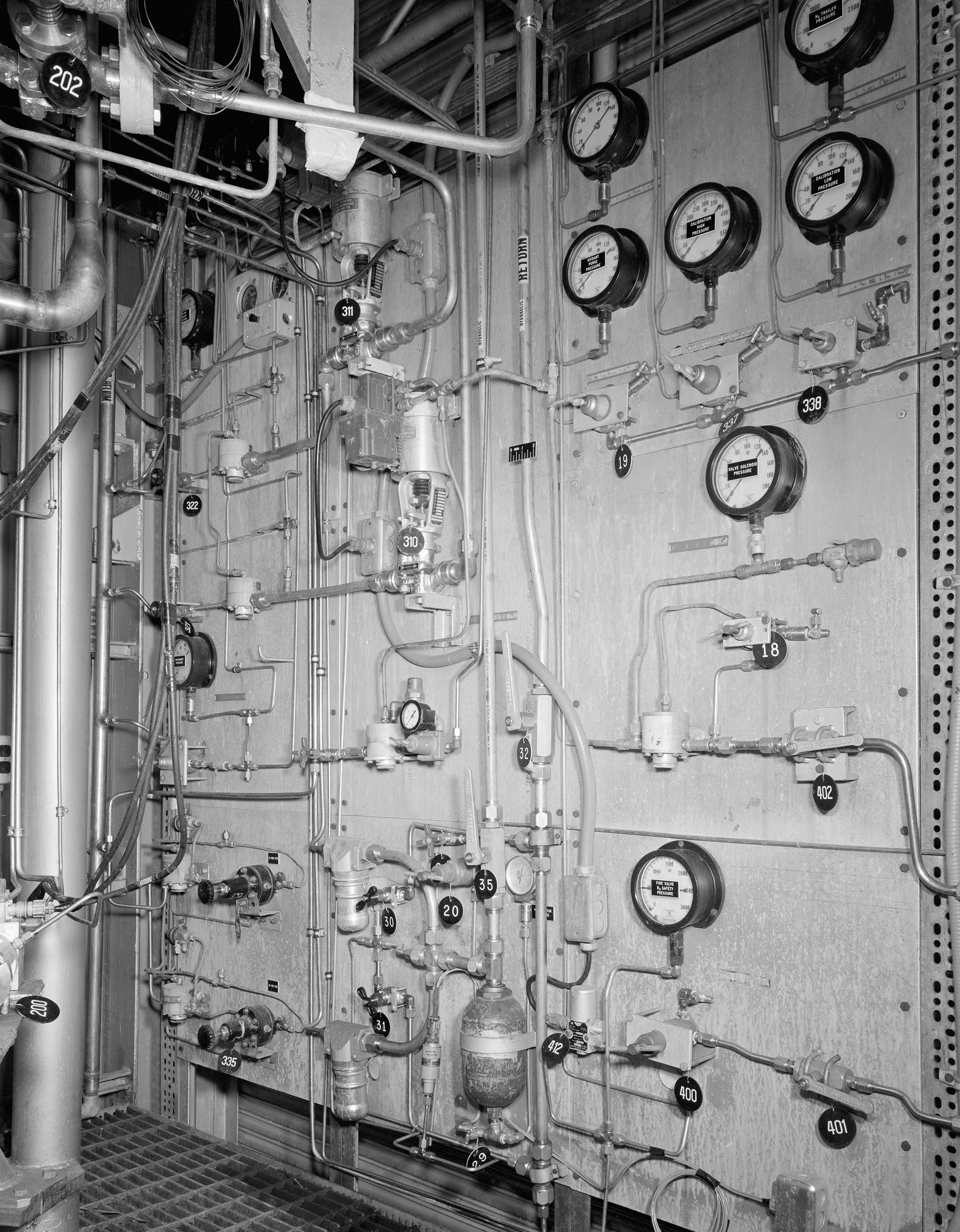
Operation:The operation of J–2 was similar to J–1. The test engineers in the control trailers adjusted the propellant pressure rates then initiated the test. The propellant flow and chamber pressure were closed-loop systems with automatic controls. The engine fired briefly and expelled its exhaust into the atmosphere.
Tests: Researchers ran a gaseous-hydrogen/liquid-fluorine engine at J–2 and studied throttling and combustion instability in a liquid-oxygen/liquid-hydrogen pressure-fed engine. Researchers also used J–2 to study the heat transfer to and from the hydrogen in regeneratively cooled nuclear rocket nozzles.
- 1961 Gaseous-hydrogen/liquid-fluorine engine
- 1962 Liquid-oxygen/liquid-hydrogen pressure-fed engine
- 1963 Throttling of a liquid-oxygen/liquid-hydrogen engine
- 1965 K Site 13-ft tank system
Documents

J–3—Vacuum Environment Facility
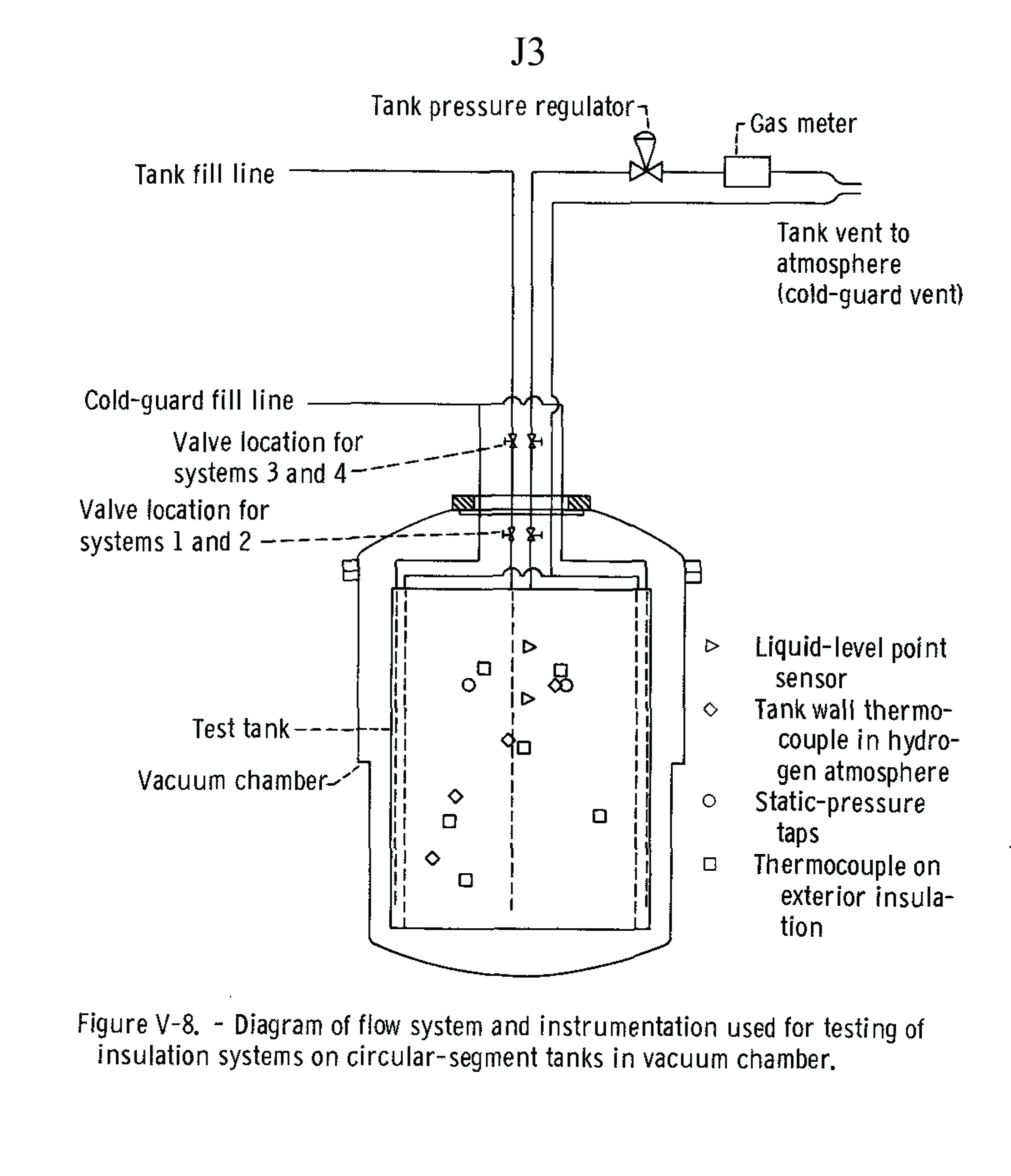
J–3 was designed to test liquid-hydrogen propellant tank durability and insulation systems in simulated space conditions. This test stand was initially the center’s only facility capable of rapid pumpdown testing.
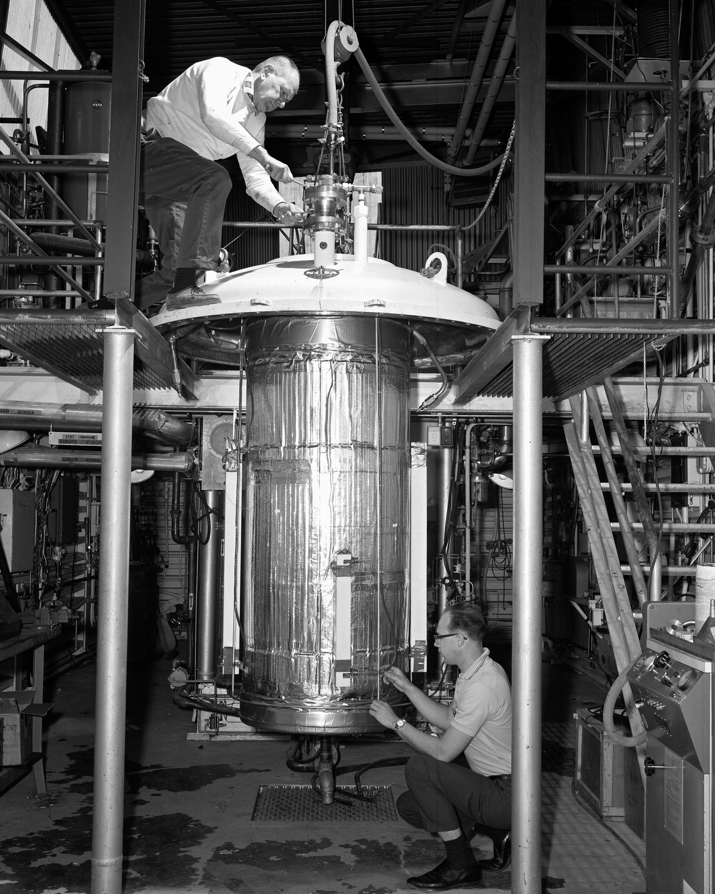
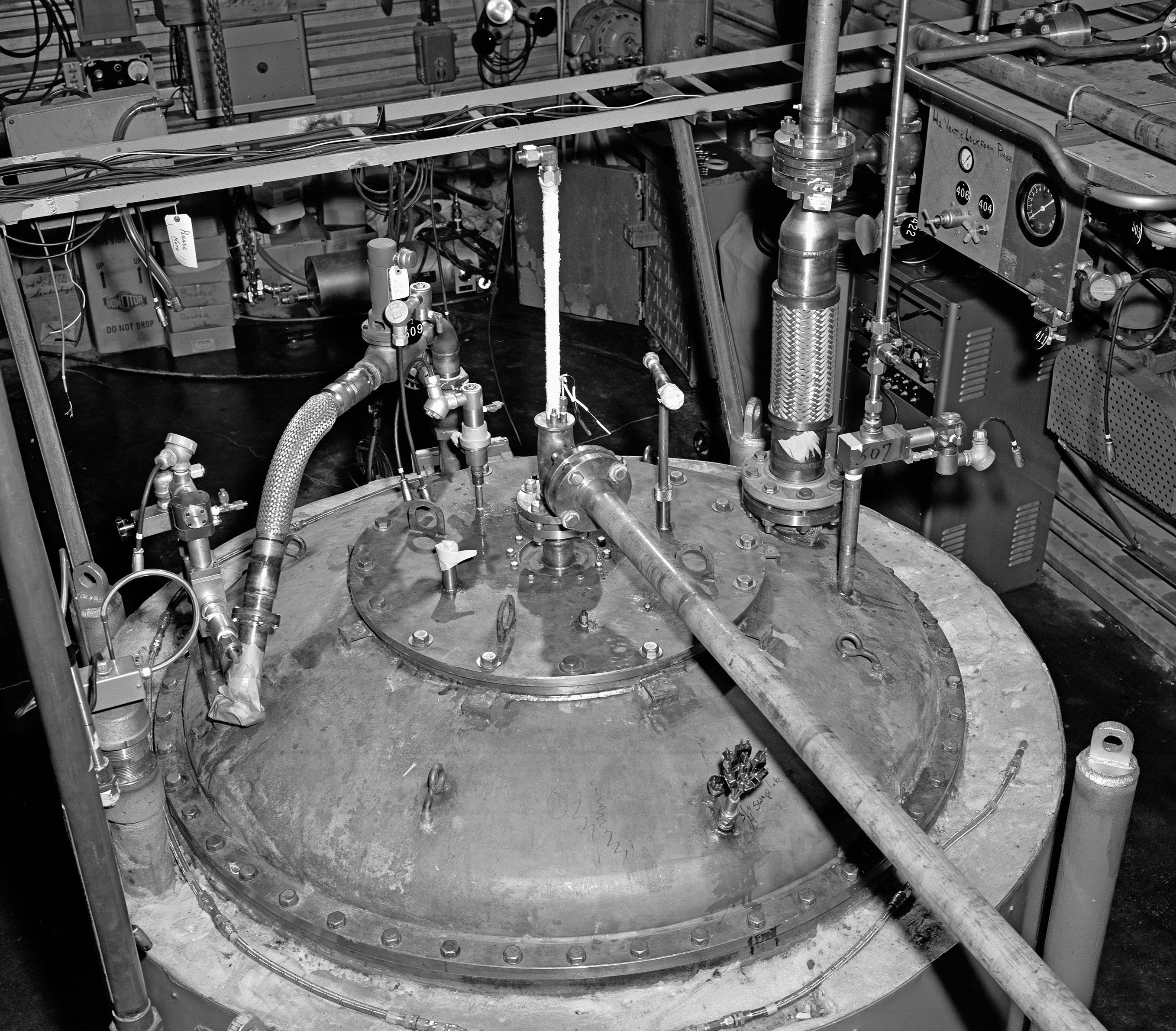
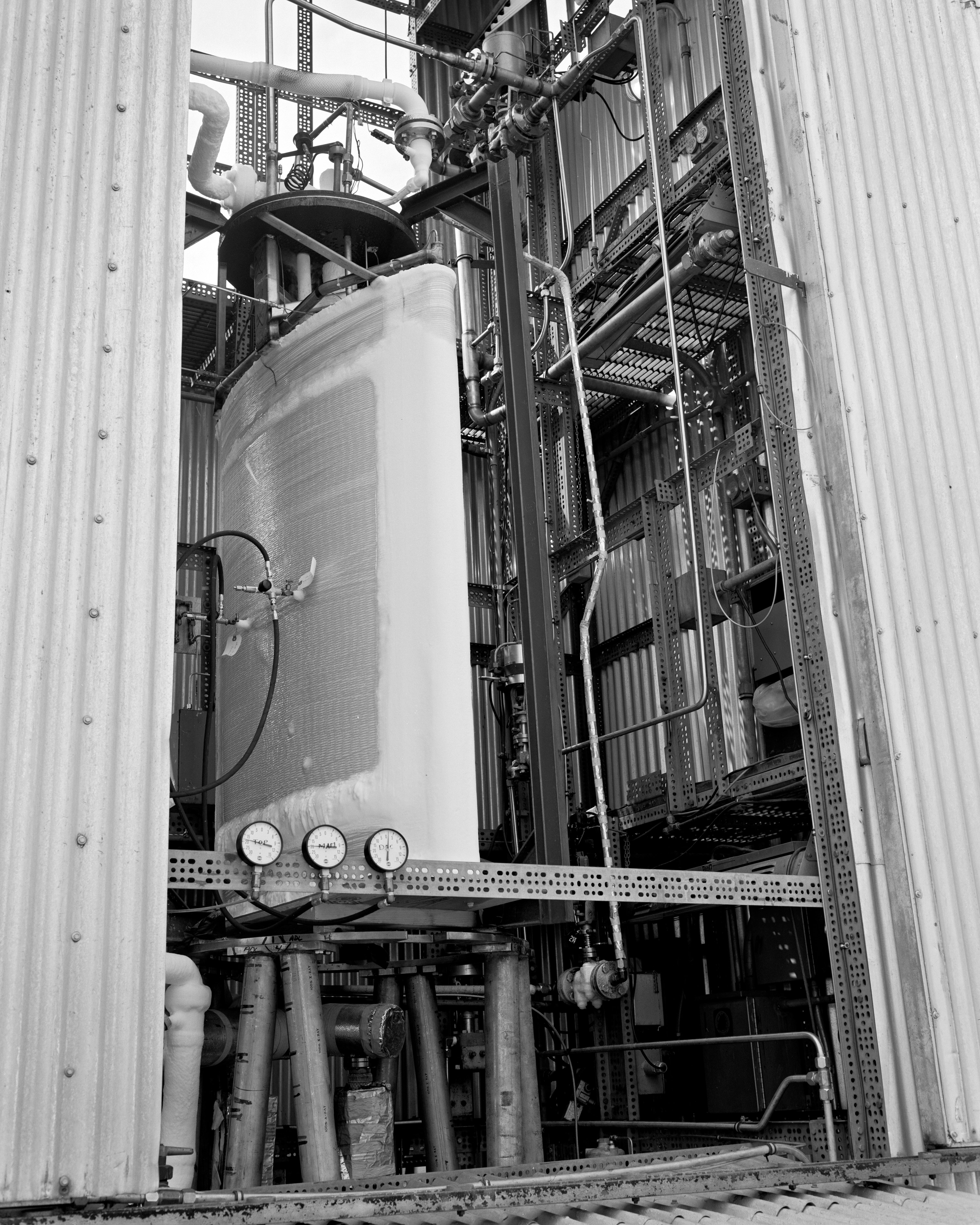
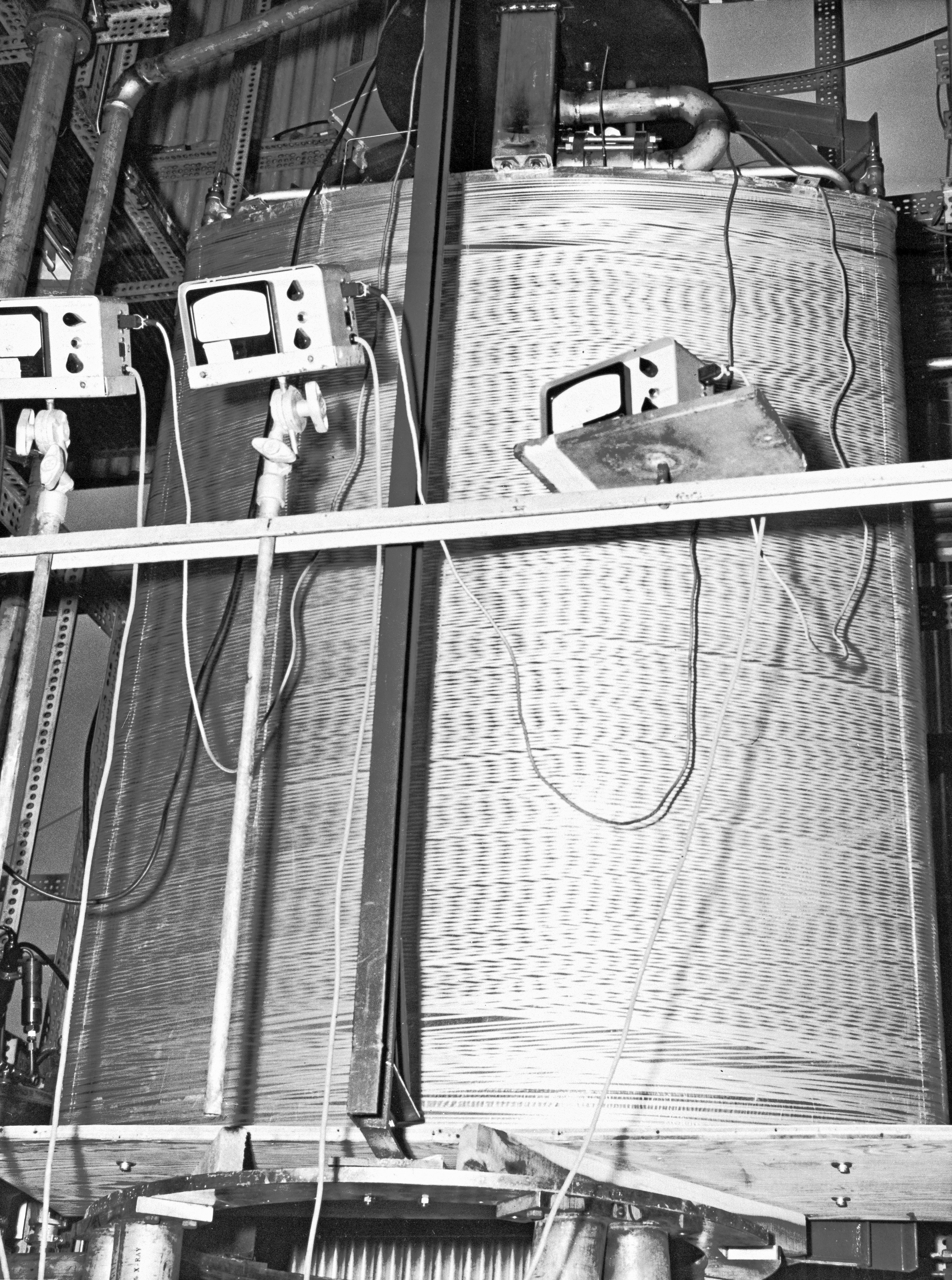
Physical Description: J–3 was located in the souththeastern half of J Site’s main building. This stand contained a modest-sized cylindrical zero-leak high-vacuum chamber in which small propellant tanks were installed. The fill line and vent line entered from the top. J–3 and J–4 shared the same hydrogen flow system.
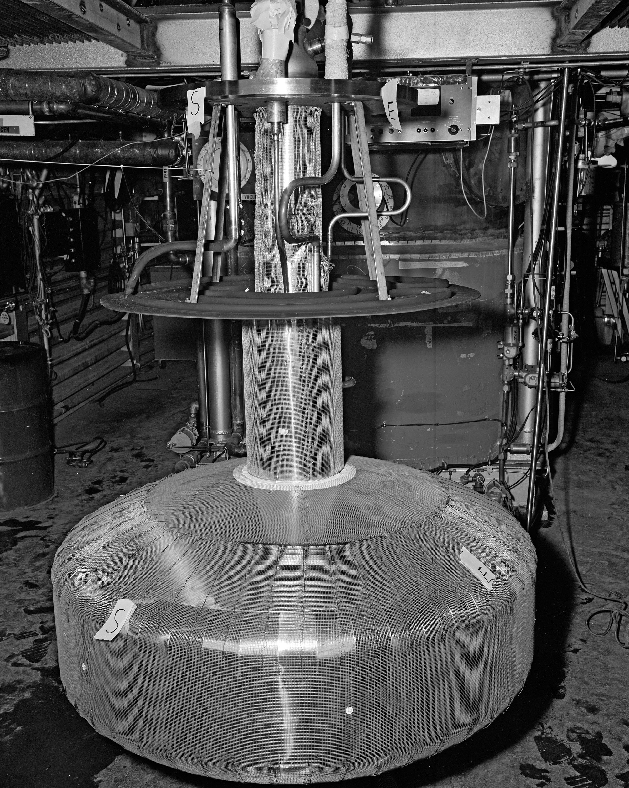
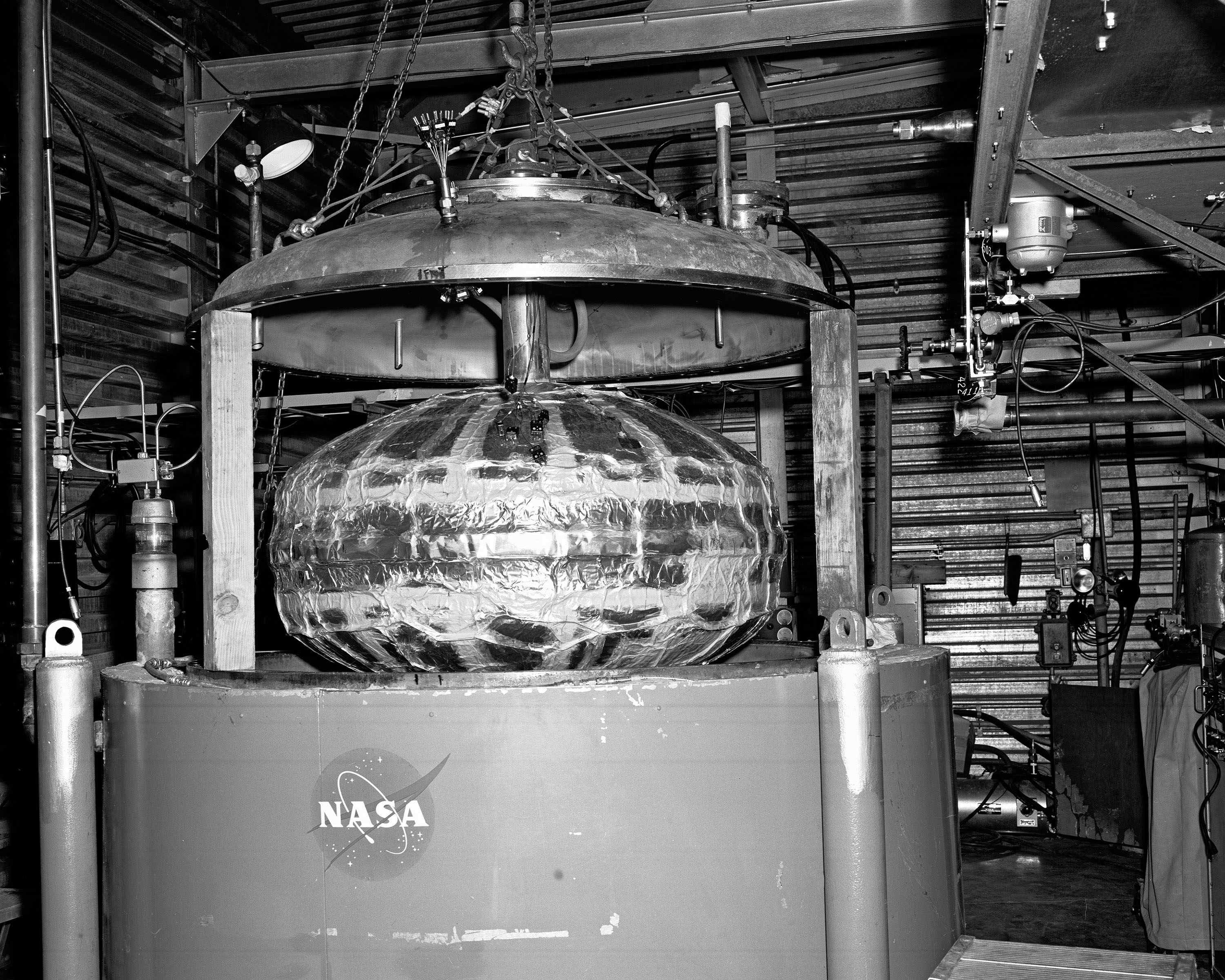
Operation: The staff hung the experimentally insulated tank from its neck inside the J–3 vacuum chamber. After purging the tank, they then filled it with liquid hydrogen and allowed it to stabilize. A mechanical pump reduced the chamber’s pressure level to simulate high altitudes. Infrared lamps simulated solar heating on one side of the tank. The operator then allowed the propellant to boil off to measure the performance of the insulation system.
Tests: Researchers used J–3 to test the thermal retention capability of various tank insulation systems, including the Linde superinsulation, Lewis Research Center’s constrictive wrap and self-evacuating insulation, and foil systems from the Arthur D Little Company.1963–64 Linde superinsulaton
- 1963–64 Centaur constrictively wrapped tank
- 1964 Arthur D. Little gold Mylar insulation
- 1966–67 Linde Self-Evacuating Multilayer Insulation (SEMI)
- 1966–68 Arthur D. Little insulation
- 1968 Copper heat transfer tank
Documents
- J3 Status Reports (1961-68)
- Compressed Multilayer Insulation System for Rocket (1963)
- Ground Hold Study of Insulation Systems for Hydrogen Tanks (1965)
- External Insulation System for Hydrogen Tanks (1965)


J–4—Tank Test Facility
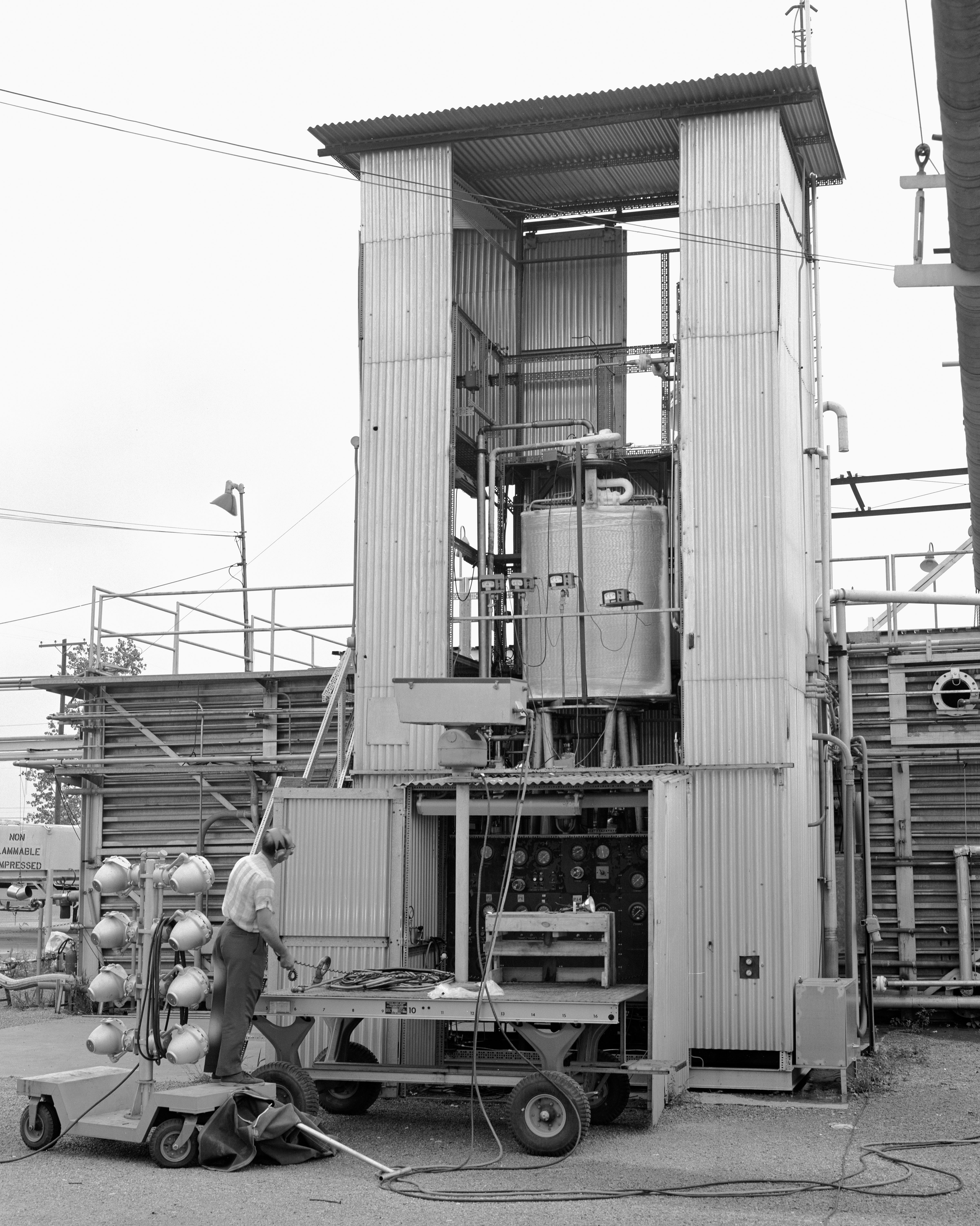
J–4 was a vertical test stand designed to study loading issues and the performance of various insulation systems in ground-hold situations.
Physical Description: J–4 was a vertical semi-enclosed test stand located off the eastern corner of the main J Site structure. The approximately 25-ft-tall stand contained experimental oxidizer and fuel tanks mounted above one another. The tank structure consisted of an inner shell, insulation, and outer shell. J–4 and J–3 shared the same hydrogen flow system.
Operation: The staff loaded the experimental tank into the stand and purged it with nitrogen gas and helium. They then flowed the liquid hydrogen and opened the tank’s vent valve. They allowed the liquid to boil off to measure the insulation system’s effectiveness. The operators conducted the tests from the J Site control trailer.
Tests: Researchers used J–4 used to test Goodyear, Linde, and Arthur D. Little insulation systems, and they proposed jettisonable and constrictively wrapped insulation for the Centaur rocket.
- 1962 Goodyear insulation system
- 1963 Linde superinsulated tank
- 1963 Centaur constrictively wrapped tank
- 1964 Arthur D. Little gold Mylar insulation
- 1964 Centaur jettisonable insulation system
Documents


J–5—Materials Compatibility Facility
The Materials Compatibility Facility (J–5), also known as the Fluorine Hydraulics Laboratory, was designed to test the durability of materials subjected to high-pressure fluorine or fluorine-oxygen flow. NASA added a stand outside the facility to study fluorine’s interaction with other materials in spill conditions.
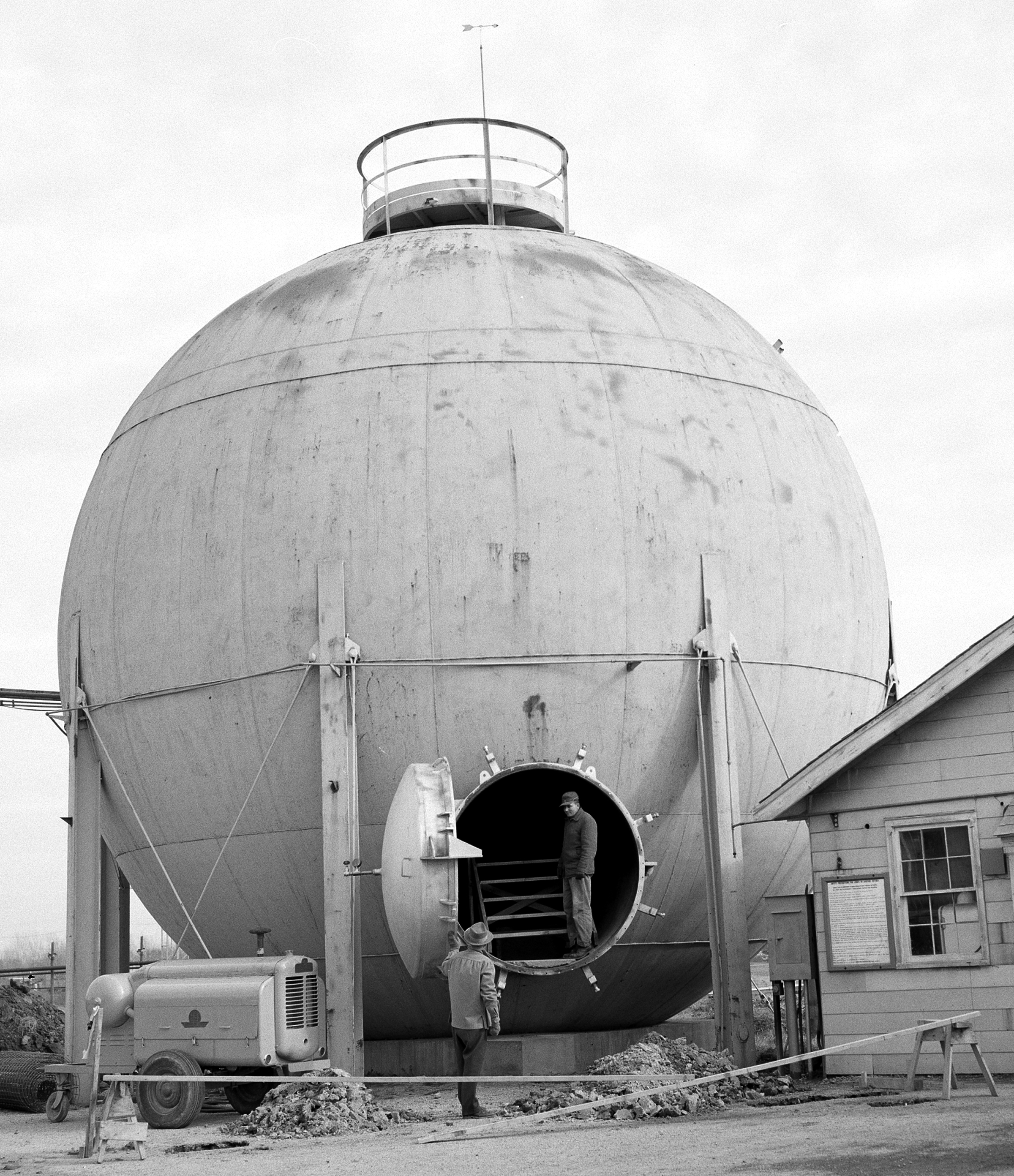
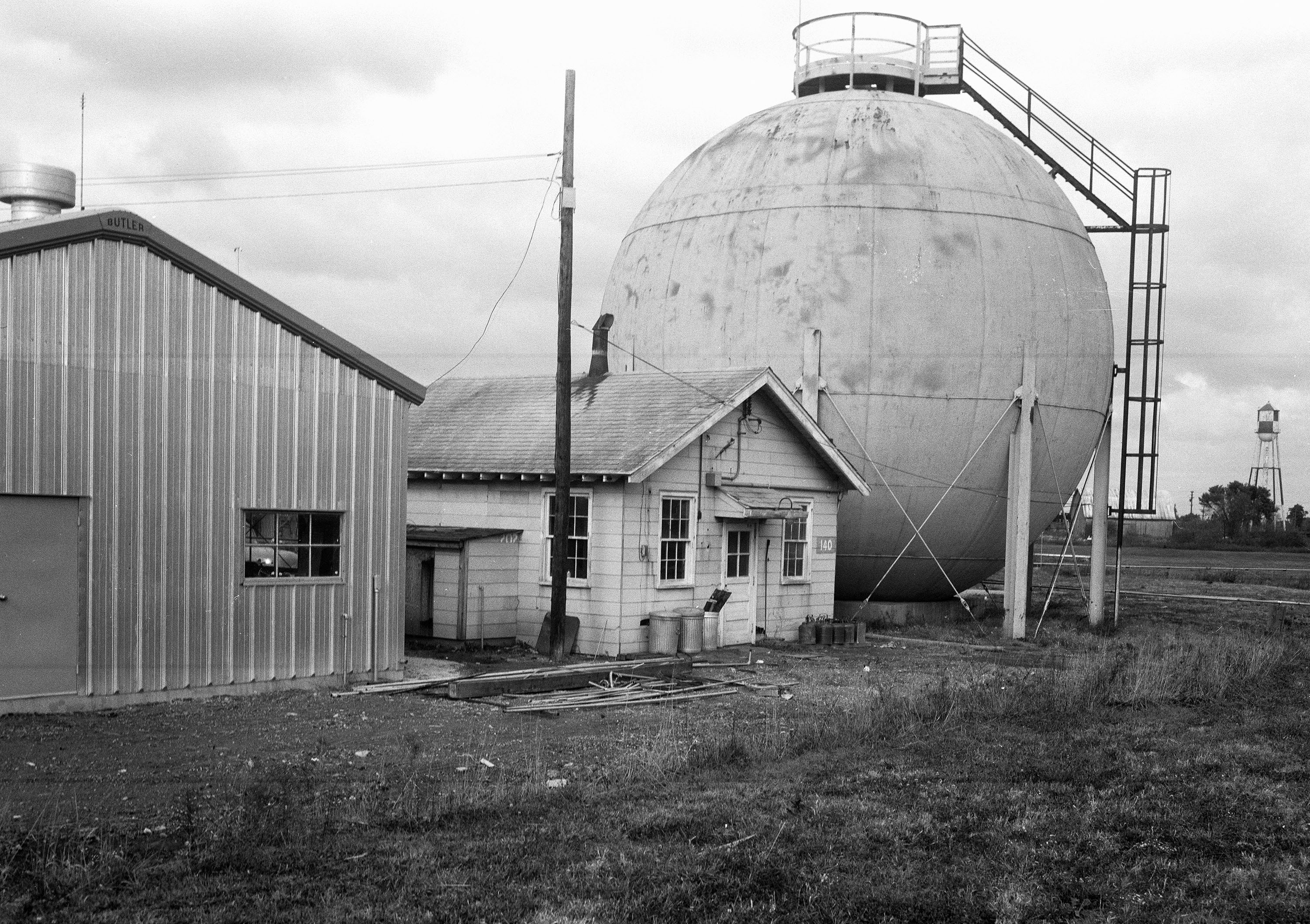
Physical Description: The J–5 dynamic materials compatibility test rig was enclosed in a 38-ft-diameter steel hortonsphere that had a poured-concrete floor to provide a level working surface. The rig’s test section was located between a supply and receiver tank. External to the facility were a separate control room, shop, safety showers, and gas storage. The control room, which was located just east of the facility, was inside a cylindrical tank buried in an earthen mound for protection. NASA added an elevated stand northeast of the facility for spill testing. This stand included an elevated 3.5-gal stainless steel tank with a 4-in.-diameter spill pipe that traveled downward through an aluminum blast shield and into a spill pan.
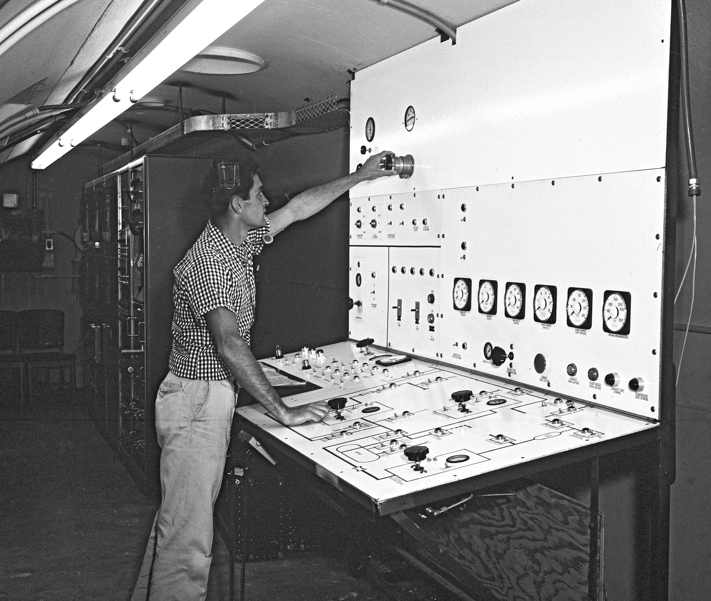
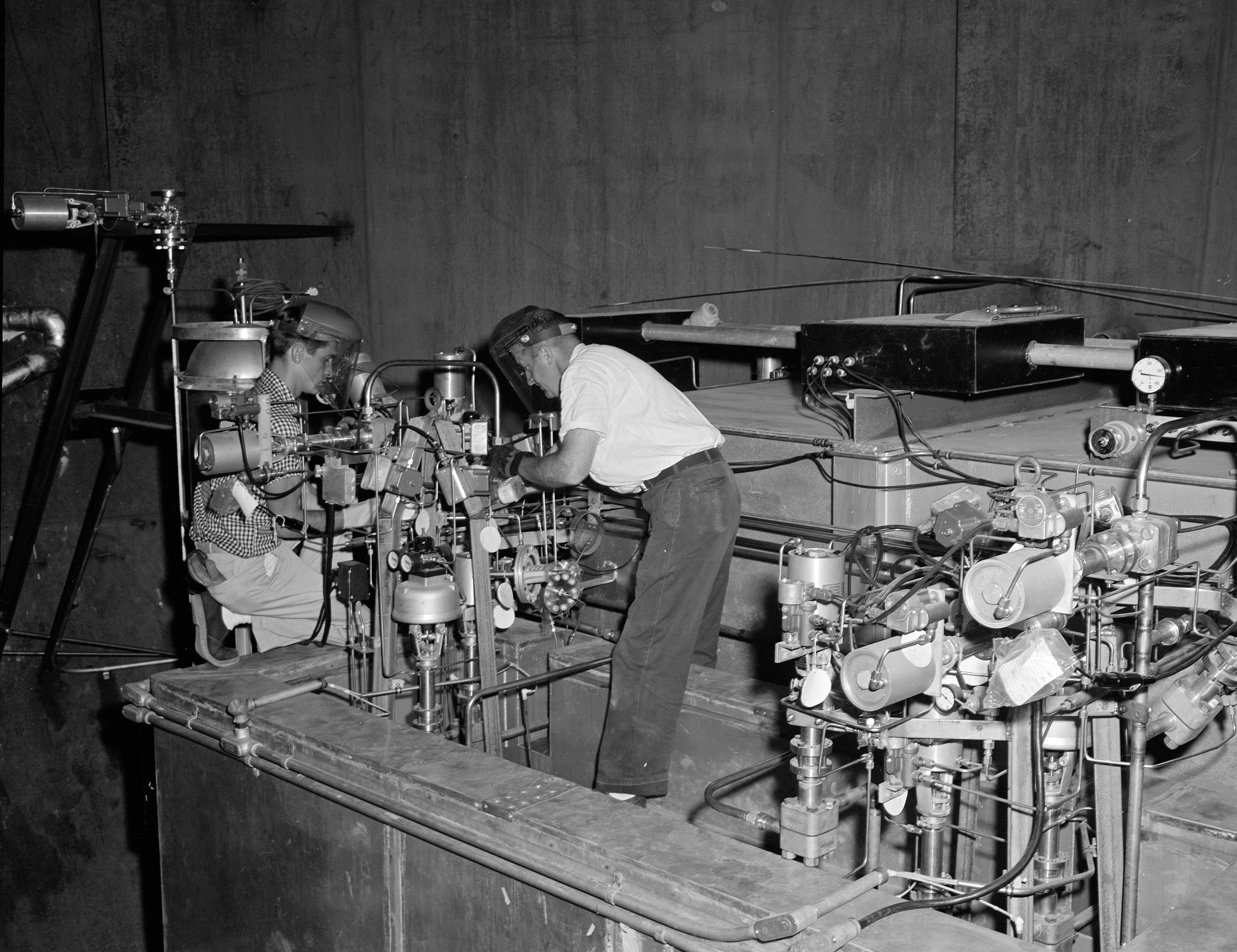
Operation: Two flanges secured the materials sample in the test section, which was immersed in liquid nitrogen. The staff wrapped burn wire around the test section to automatically shut down the run if fire was present. The operators, located nearby in the J–5 control room, controlled the flow rate as the liquid fluorine passed from the supply tank, through the test section, and into the receiver tank. The spill tower tests released the liquid fluorine from the elevated tank and allowed it to splash into a pan filled with various materials to document the reaction.
Tests: Researchers used J–5 for two series of tests. One studied the ability of different materials to withstand high-pressure fluorine flow to determine if they were suited for use in seals for fluorine engines. The other analyzed fluorine’s reaction with materials typically found near storage tanks to determine what would happen with a major fluorine spill.
- 1963–64 Fluorine/fluorine-oxygen (FLOX) materials compatibility
- 1964 Fluorine/FLOX spills
Reports
- J5 Status Reports (1961-66)
- Compatibility of Materials with Fluorine Mixtures (1966)
- Reaction of Spills of Fluorine Upon Materials (1966)