B-1 and B-3 Test Stands
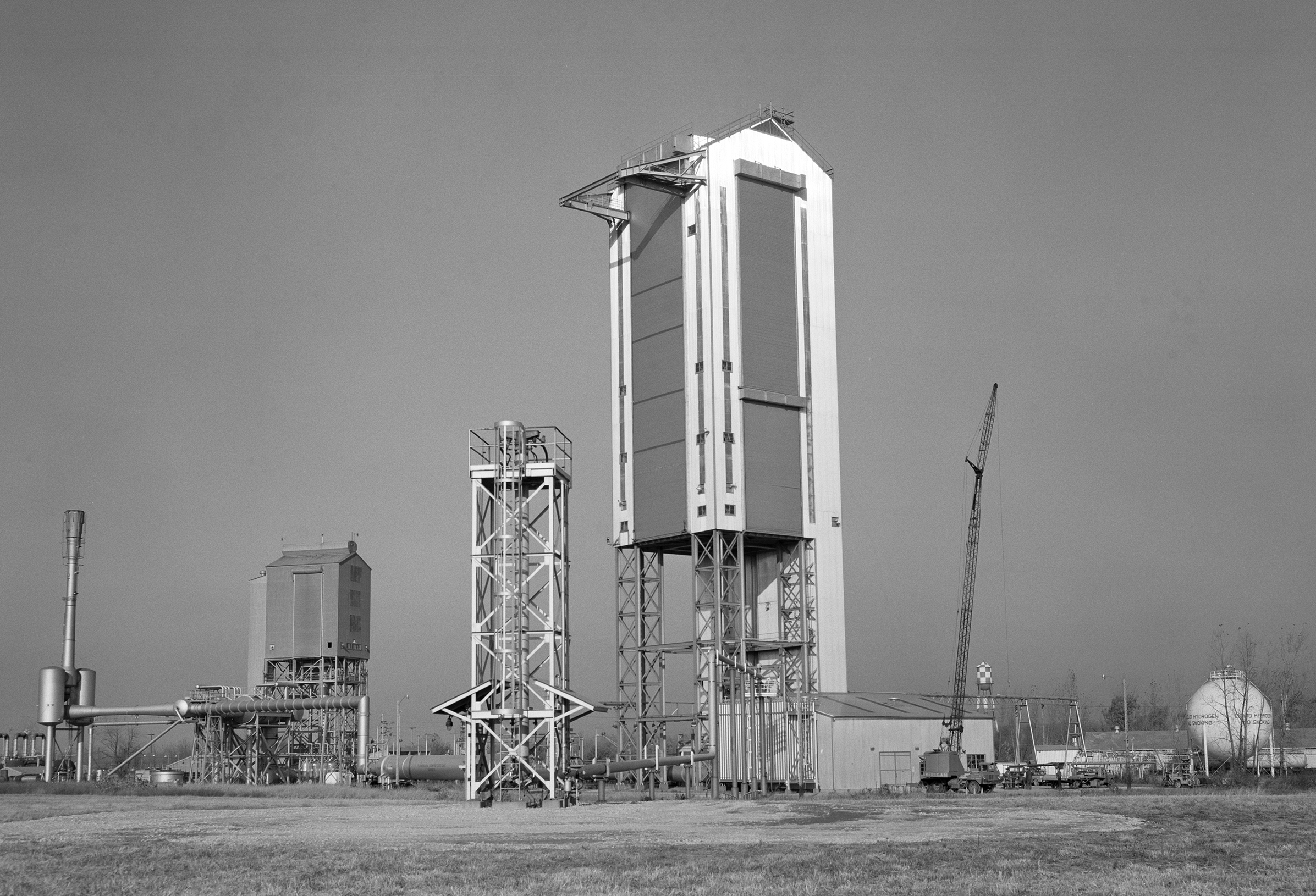
The High Energy Rocket Engine Research Facility (B-1) and Nuclear Rocket Dynamics and Control Facility (B-3) were vertical test stands with cryogenic fuel and steam ejector systems that permitted rocket fuel systems to be studied in simulated altitude conditions. Each test stand had several levels, a test section, and ground floor shop areas. The test stands relied on an array of support buildings to conduct their tests, including a control building, steam exhaust system, and fuel storage and pumping facilities.
Documents
B–1 Stand—High Energy Rocket Engine Research Facility
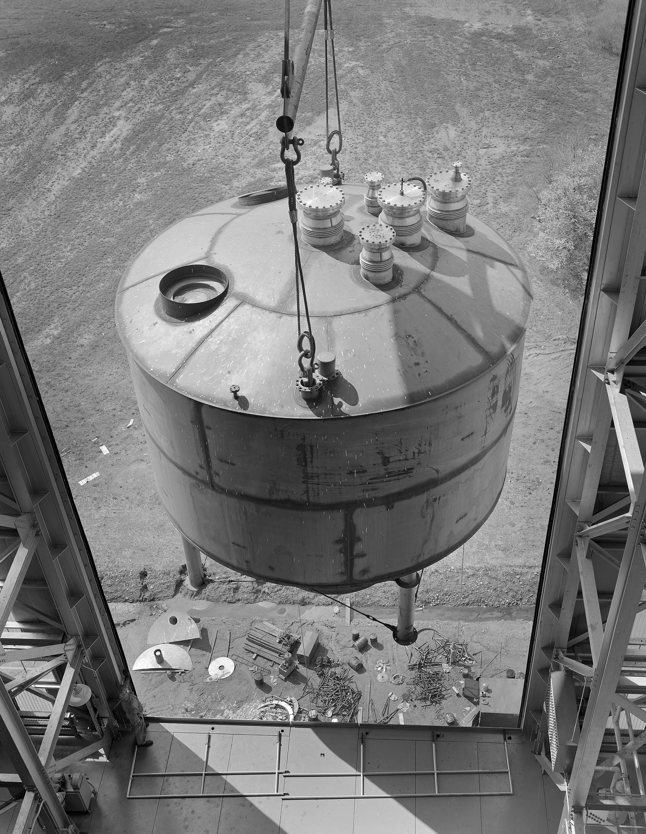
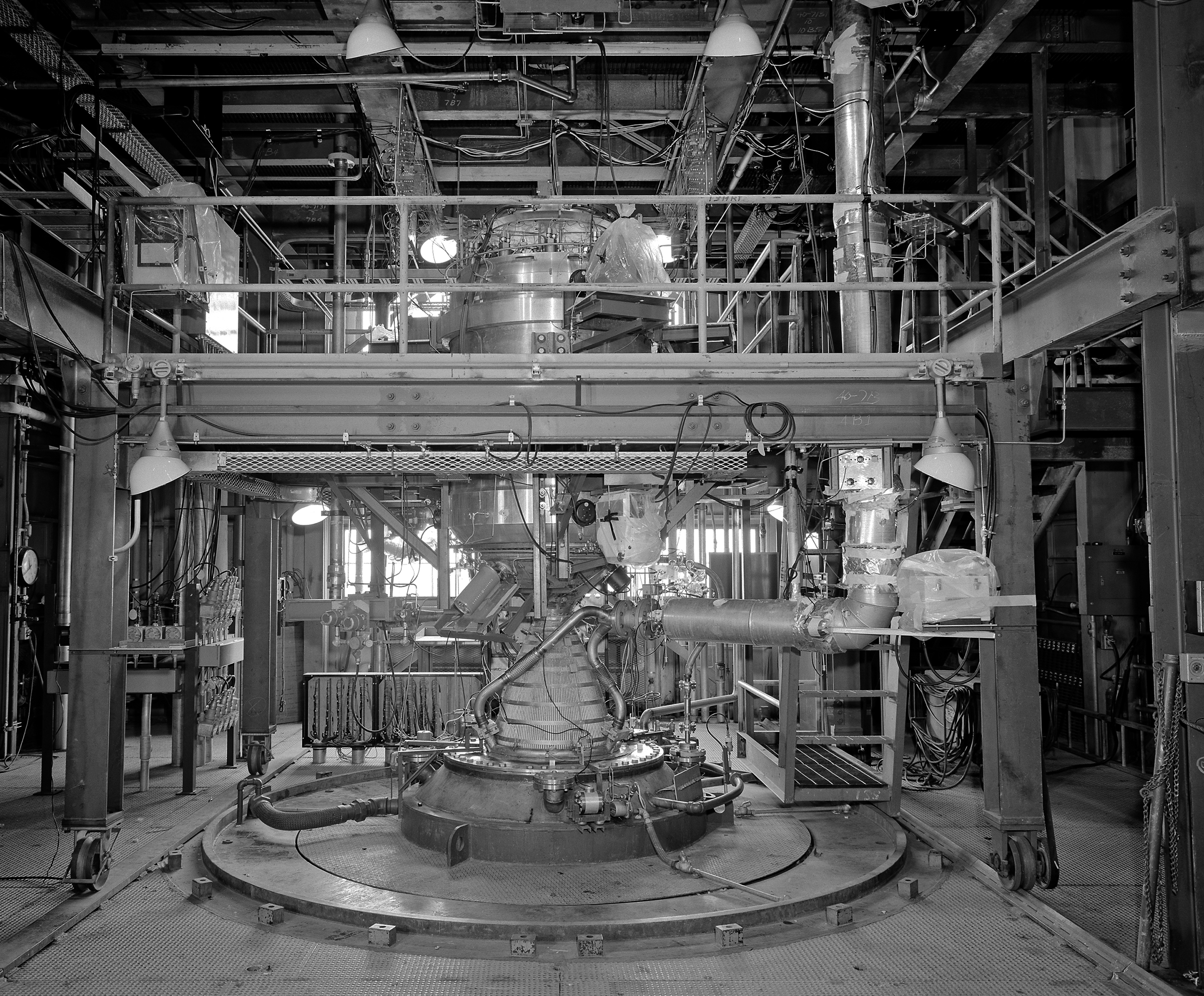
The B–1 Stand was designed for hot-firing tests of hydrogen and fluorine engines with up to 30,000 pounds of thrust at altitude conditions, although it was never used in this capacity. It had a vacuum capsule for testing entire engines in a space environment, and a steel test carriage for cold-flow tests. Researchers never utilized its engine firing capability, but they did test full-scale hydrogen pumping systems for simulated missions.
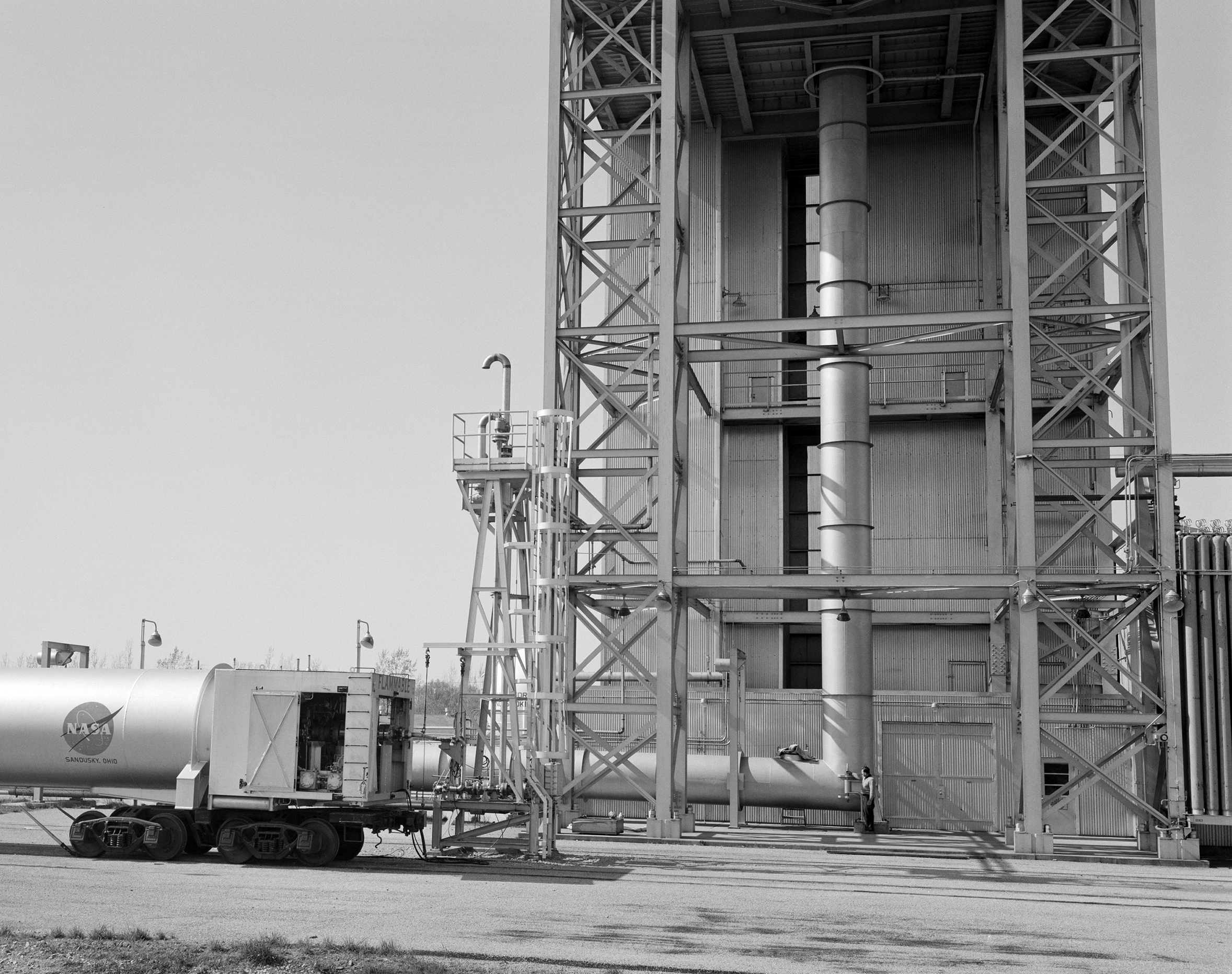
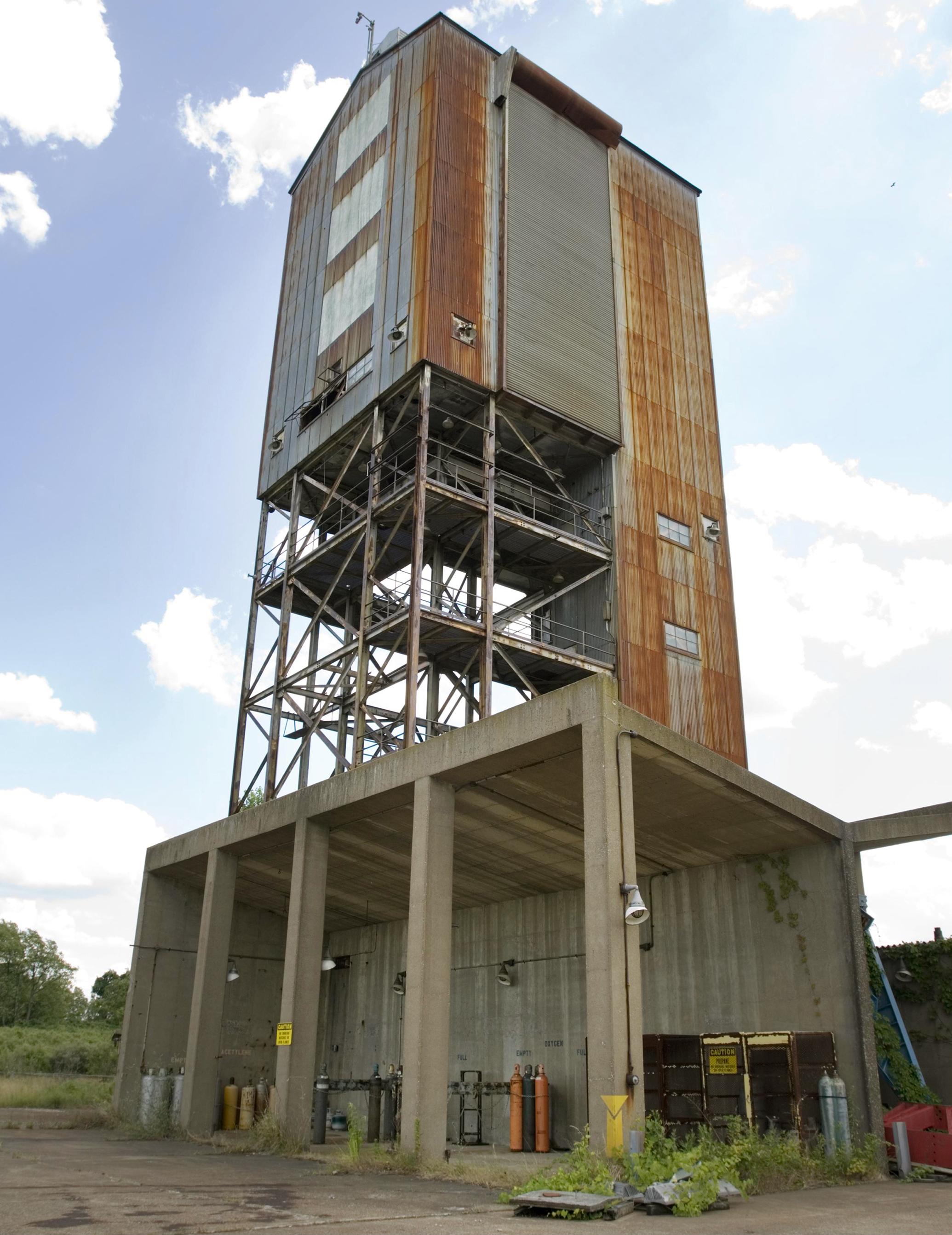
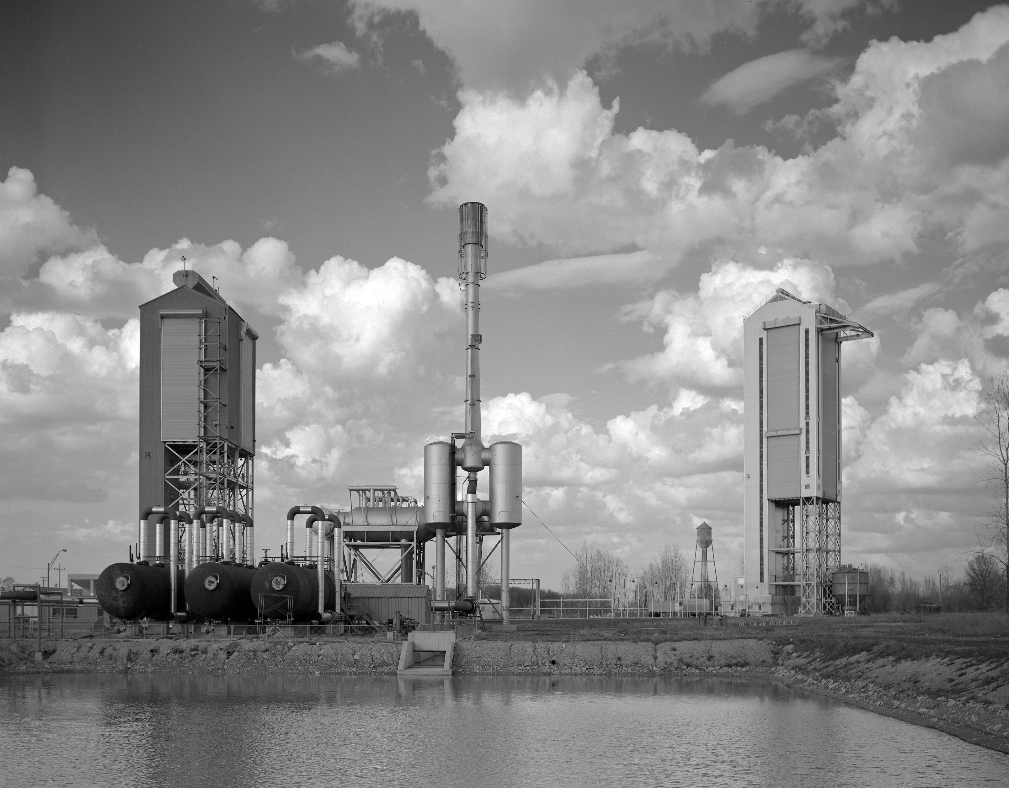
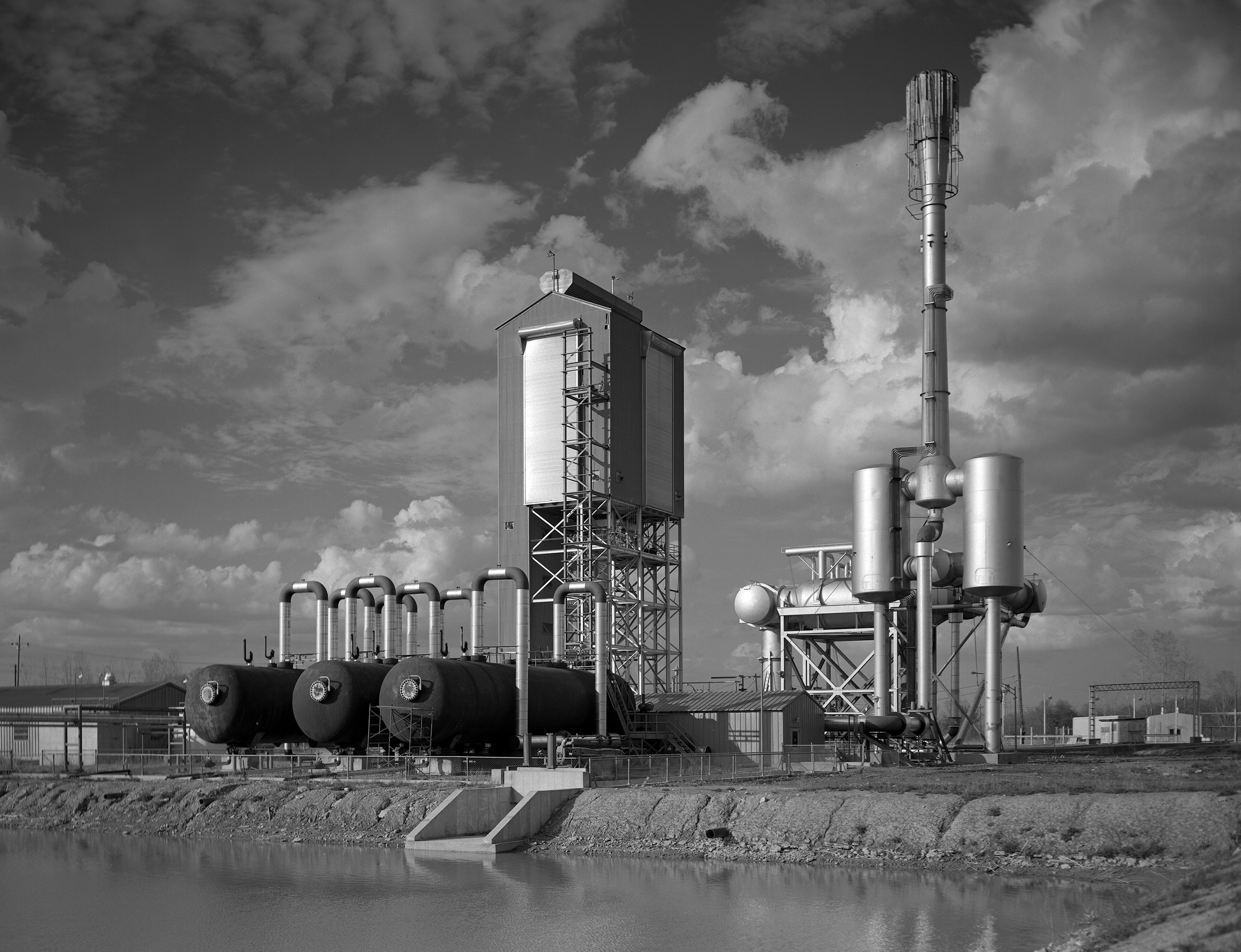
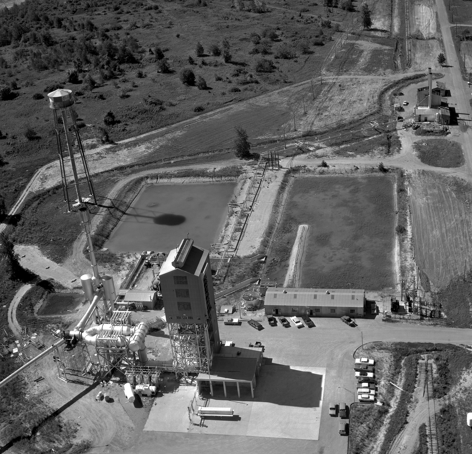
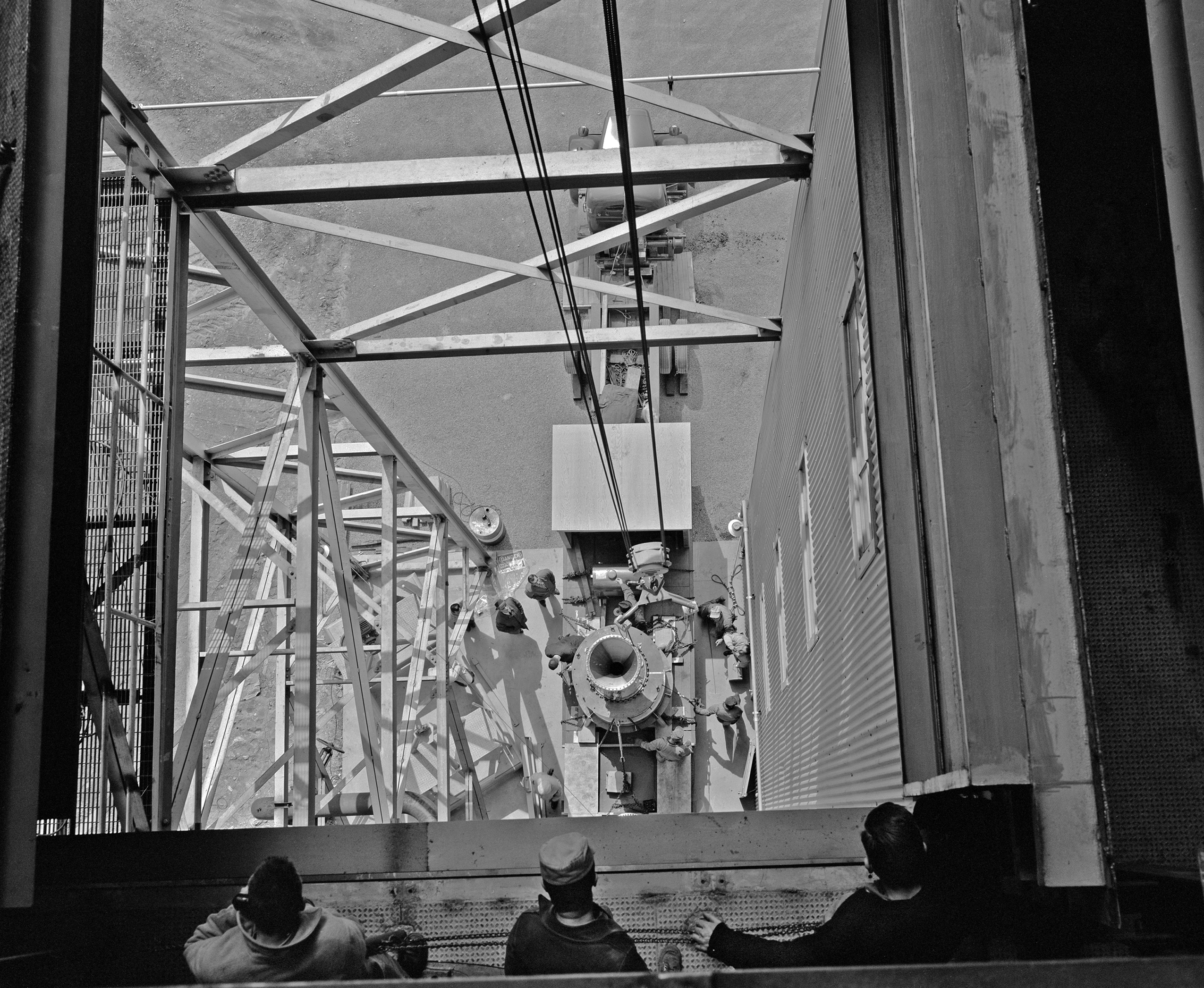
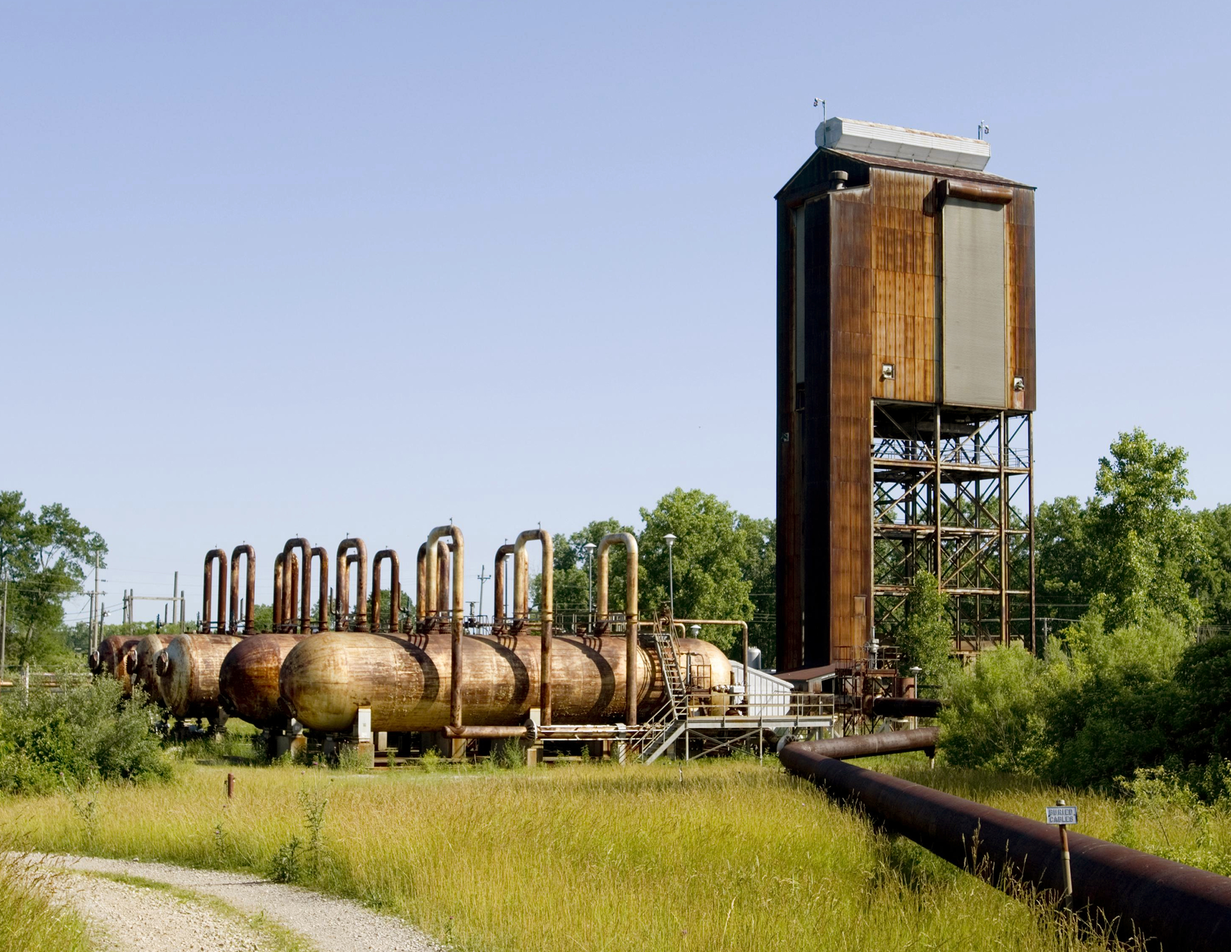
Physical Description: B–1 was located with the Nuclear Rocket Dynamics and Control Facility (the B–3 Stand) off of Box Factory Road near the southern end of the Rocket Systems Area. The 135-foot-tall vertical tower was enclosed above the 68-foot level. By 1964 the facility included roll-up doors on three sides to provide ventilation in the event of a hydrogen leak. The B–1 tower faced two rectangle retention ponds to the southwest. The steam accumulators and a steam ejector stack were linked to the southeast wall of the test stand. A rectangular single-story Pump House and a smaller Valve House stood between the test stand and the large retention ponds. A water tower was to the west of the ponds. The B–1 Stand included cryogenic fuel tanks, exhaust gas scrubbers, and large storage trailers for gaseous and cryogenic materials.
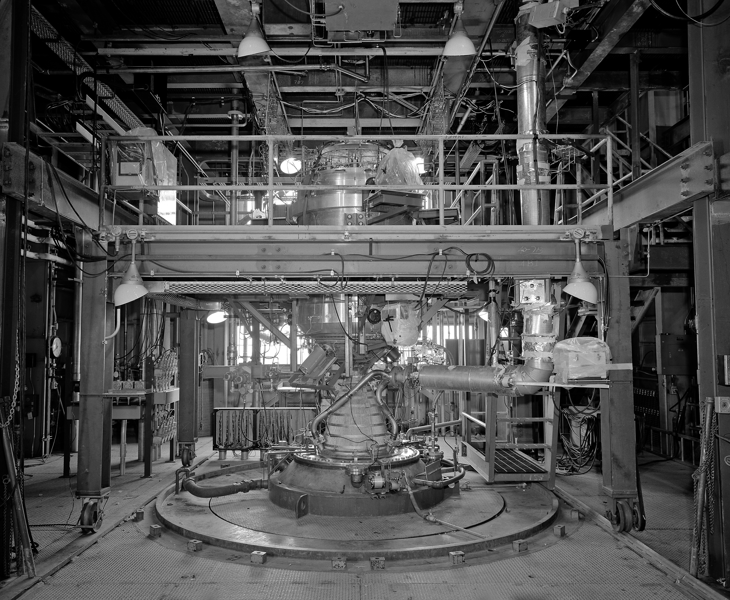
The test chamber was a 13-foot-diameter, 30-foot-tall space within the tower. The B–1 Stand included cryogenic fuel tanks, exhaust gas scrubbers, and large storage trailers for gaseous and cryogenic materials. A two-stage steam ejector provided vacuum pumping to create the low pressures of space. The facility was tied into Plum Brook Station’s [today, the Neil Armstrong Test Facility] data acquisition system.
Operation: It took two days for the Boiler House to fill the steam accumulators needed to operate the two-stage steam ejector that provided vacuum pumping to create the low pressures of space. During this period the staff installed the instrumentation, purged and chilled the propellant lines, and sequenced the run program equipment. When this was complete, the operator initiated the steam ejector system. Once the exhaust duct pressure reached 2 pounds per square inch, the operator commenced the test run, which usually lasted under 1 minute. The tests were run from the B Control Building located approximately 2,500 feet from the facilities. The facility was tied into the station’s data acquisition system in H Control.
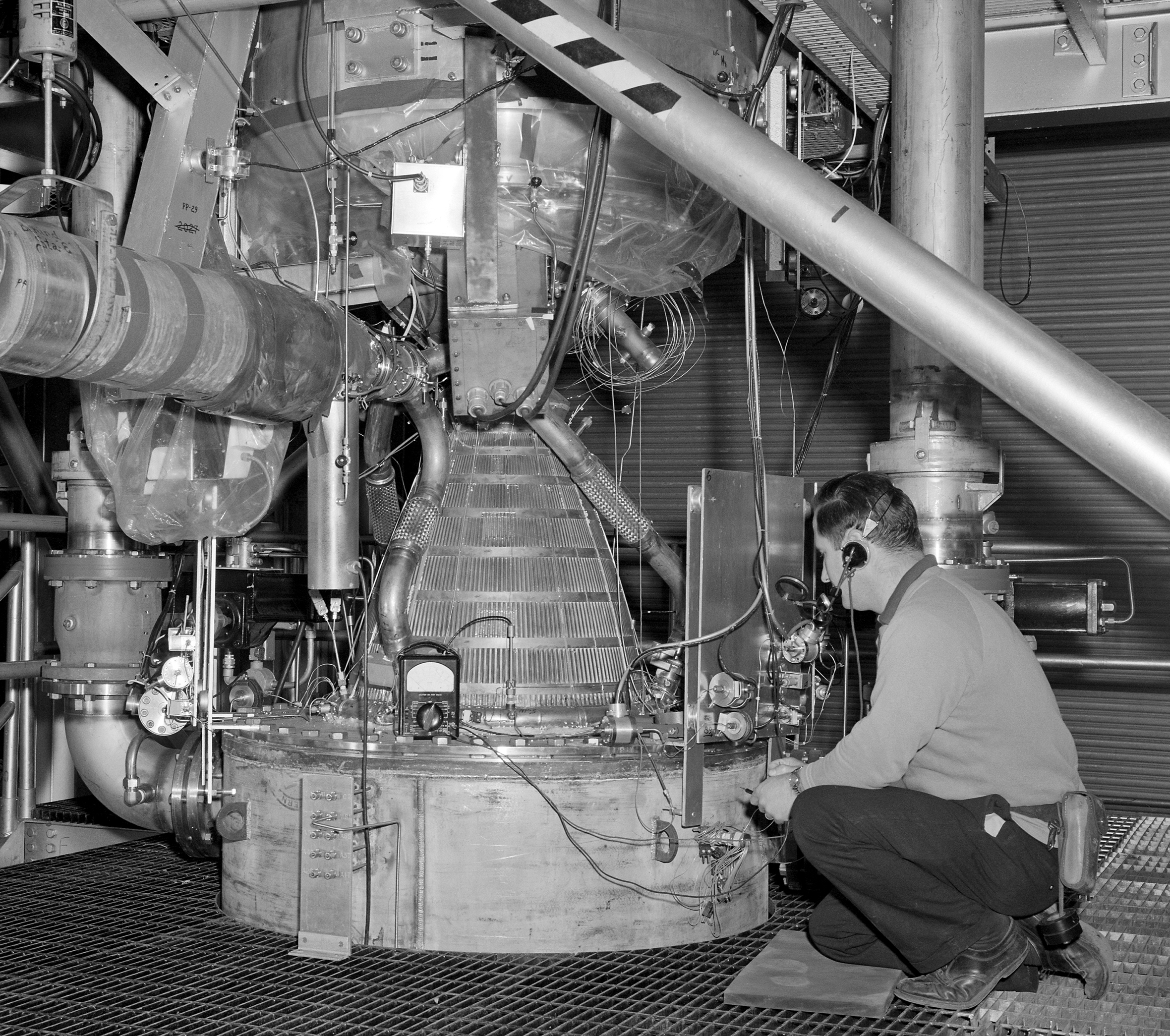
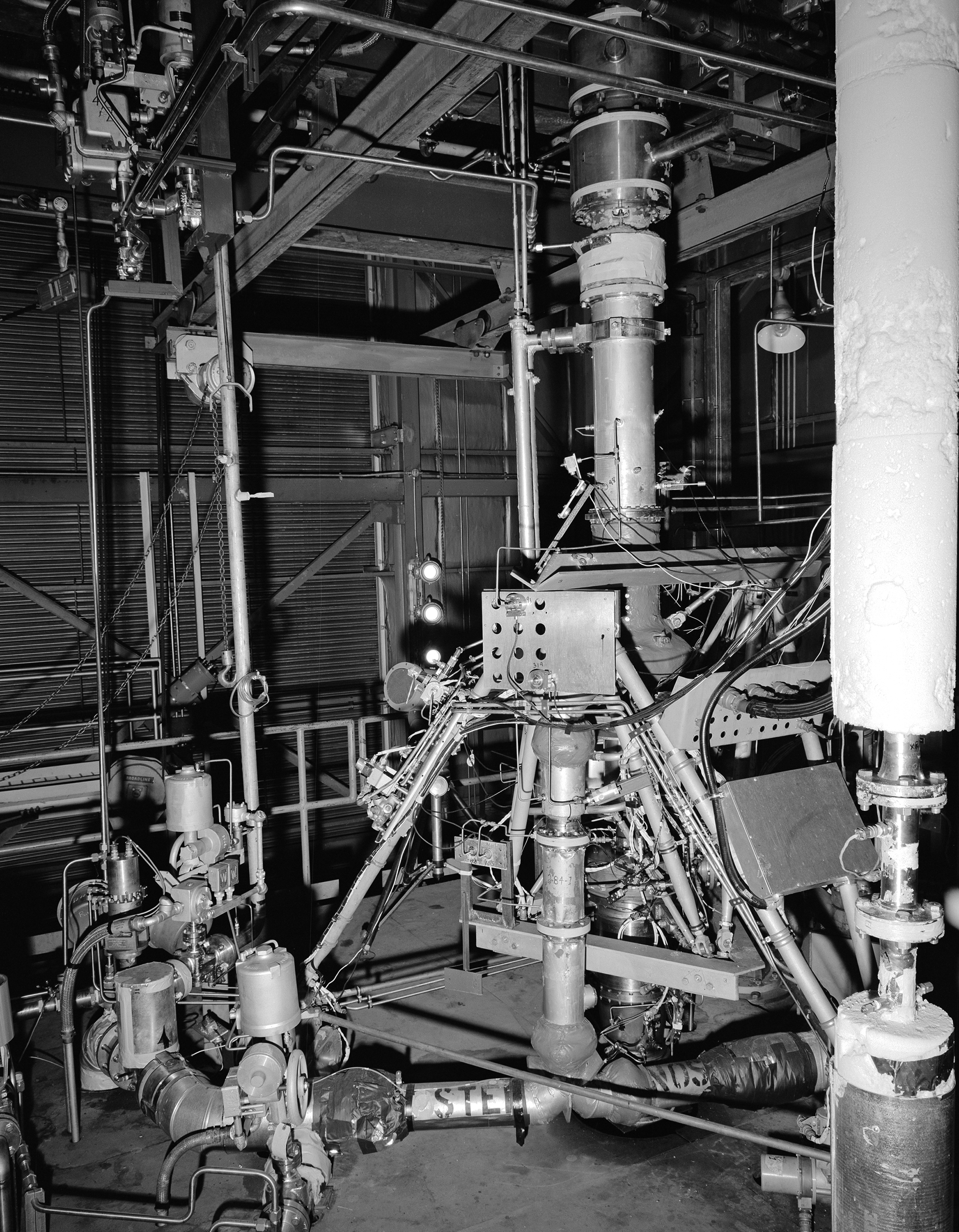
Tests: The B–1 Stand was used for extensive study of the Mark IX turbopump for the Kiwi phase of the
Nuclear Engine for Rocket Vehicle Application (NERVA) program. The B–1 tests focused on the propellant feed system, including the turbopumps, fluid instability in flow passages, and evaluation of equipment performance. Researchers also used the B–1 Stand for a series of liquid hydrogen outflow and tank-pressurization tests for the Centaur Program. The tests led to a redesign of the tank insulation that was eventually the standard used on the Centaur D, and they were an important early step in the eventual elimination of the boost pumps from the Centaur feed system.
- 1964–66 NERVA engine propellant feed tests
- 1967–69 Advanced Centaur tests
Documents
- B-1 Floor Plans and Description
- B-1 Facility Resume (1960s)
- B-1 Historic Engineering Report Description
- B-1 NERVA Apparatus Description (1964)
- B1 Stand Status Reports (1963-71)
- B-1 End Condition Statement (1973)


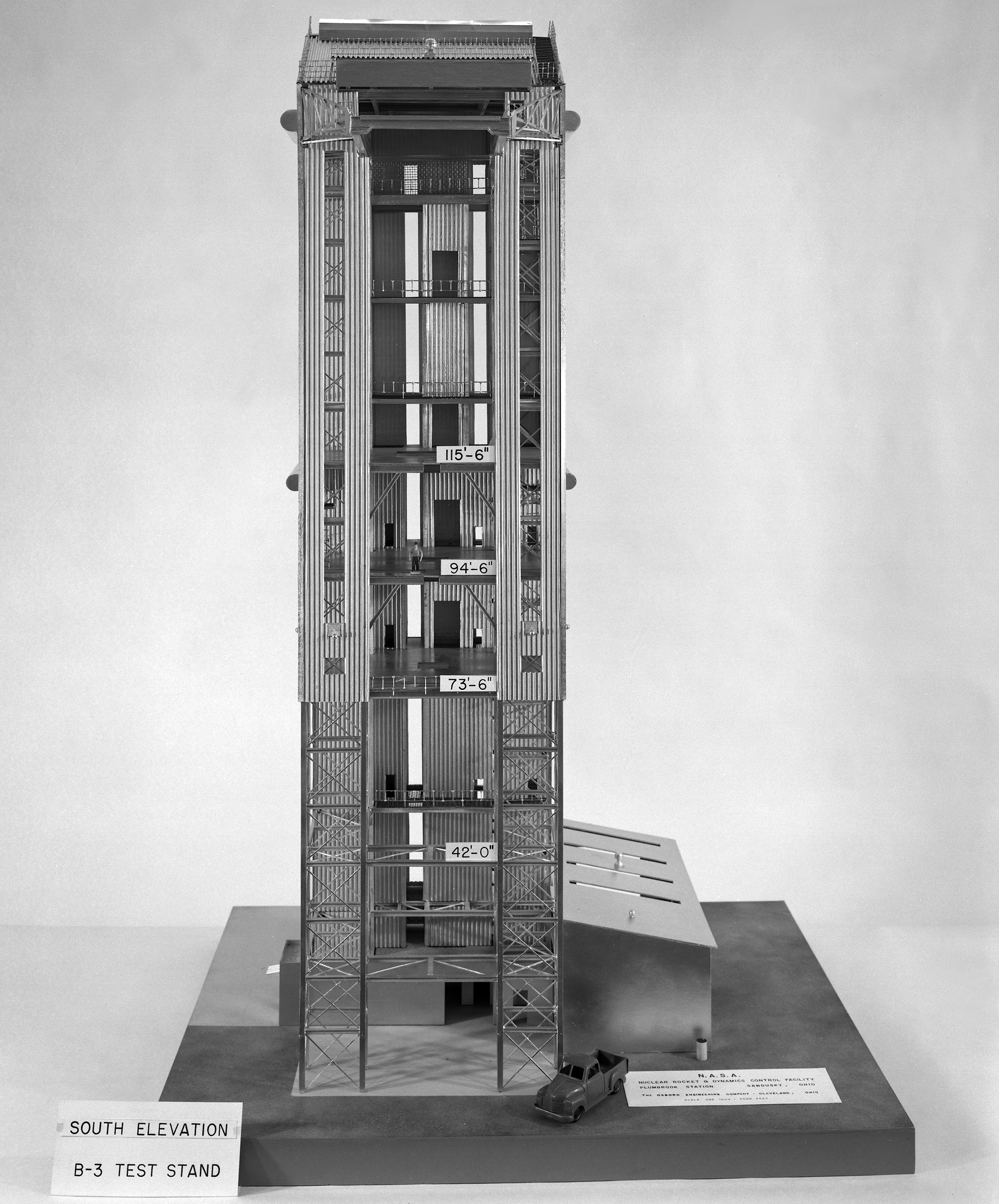
B–3 Stand—Nuclear Rocket Dynamics and Control Facility
The B–3 Stand was used to study tanking and flow systems for complete nuclear rocket engine systems in simulated altitude conditions. The rocket’s combustion chamber was pressurized to simulate an actual launch, but the engines were not fired and the reactor was not operated. The B–1 Stand facilitated the study of propellant flow systems and turbopumps.
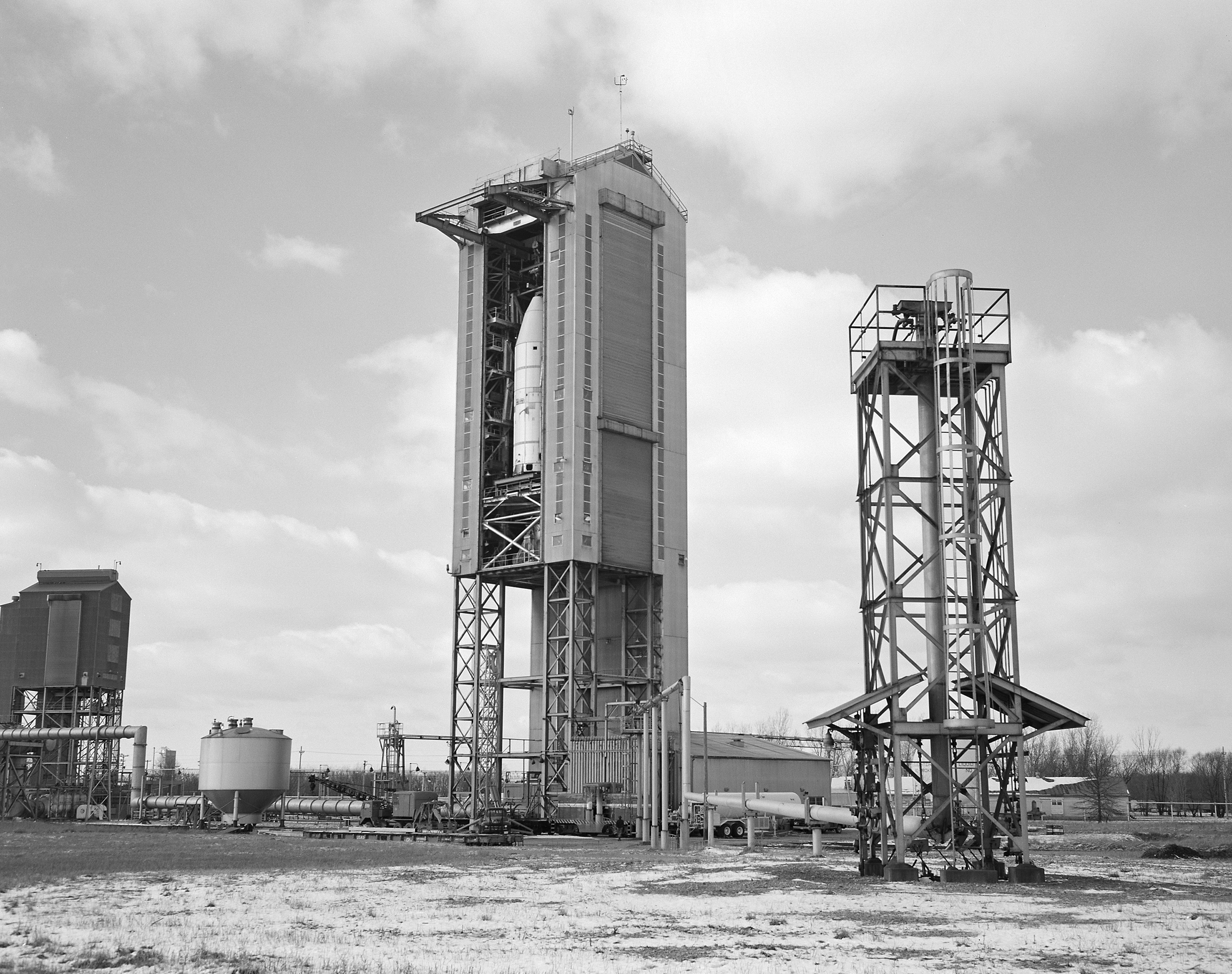
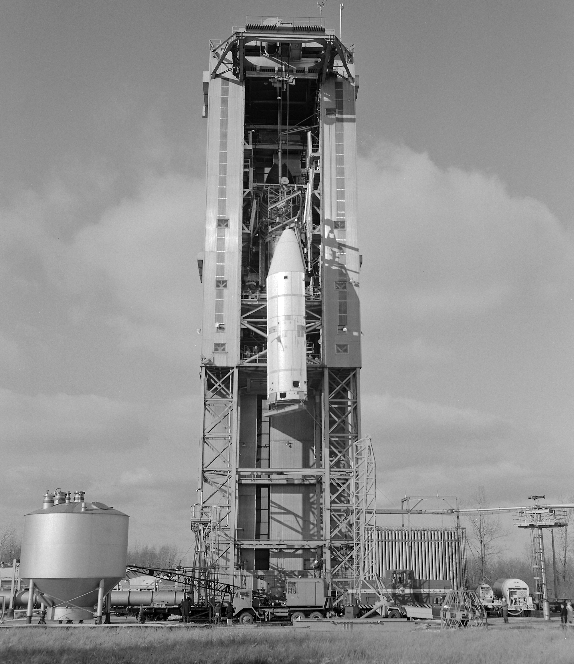
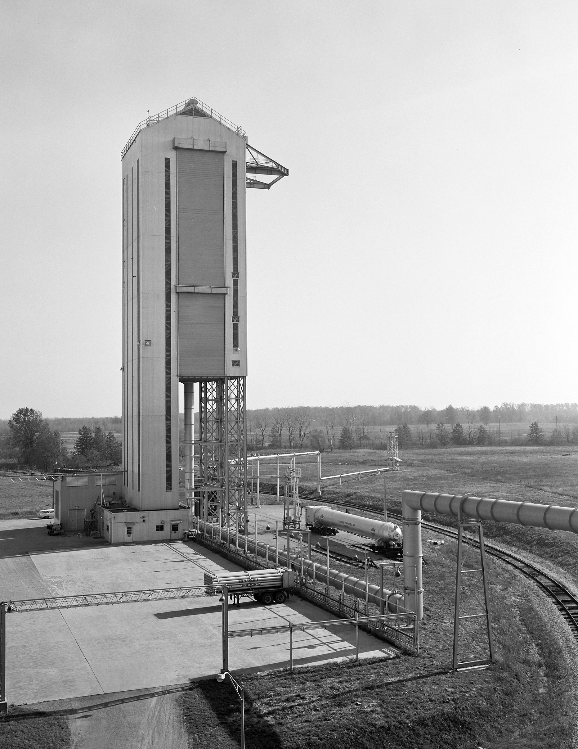
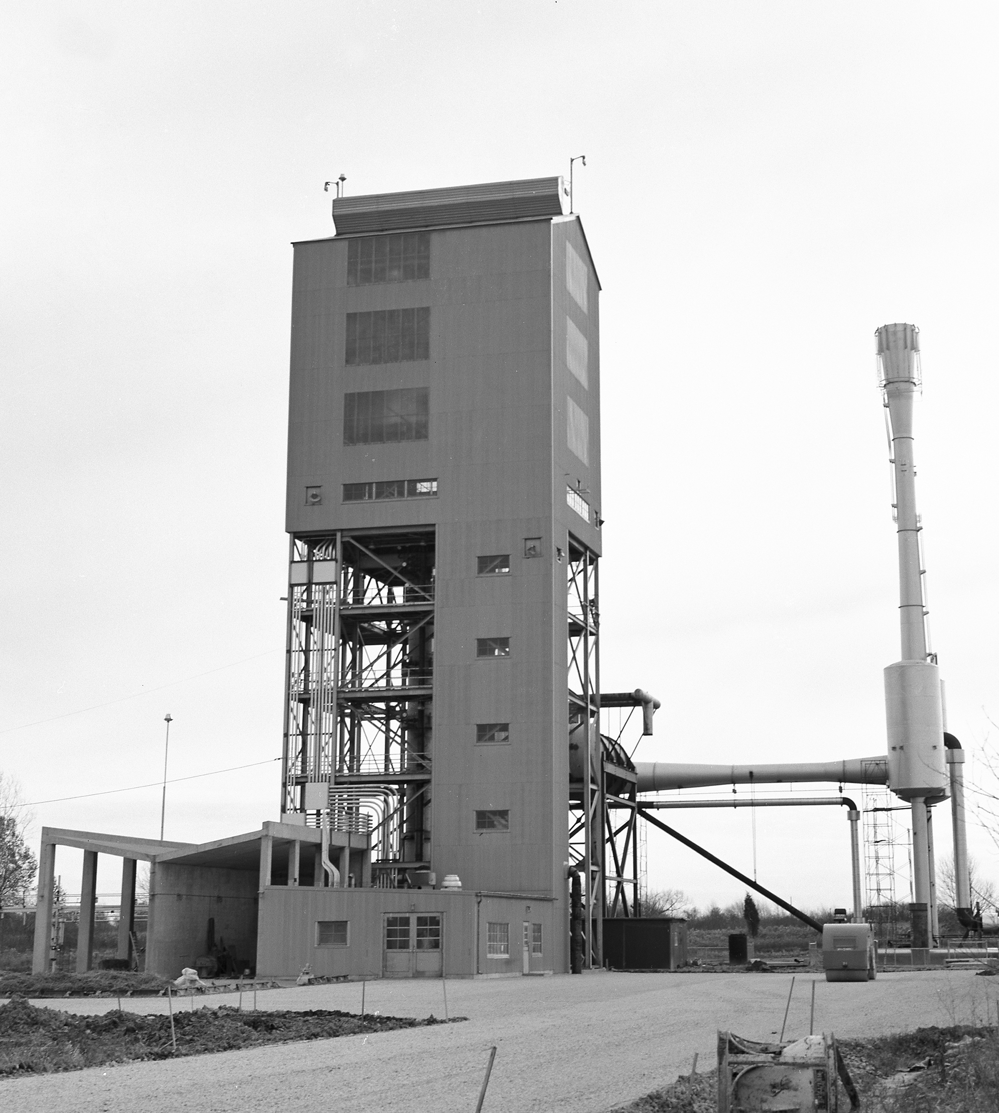
Physical Description: The B–3 Stand was located with the B–1 Stand off of Box Factory Road near the southern end of the Rocket Systems Area. At 210 feet in height, the 50- by 50-foot tower was the tallest structure at Plum Brook. The upper section, 32 by 27.5 feet in area, was enclosed above the 74-foot level. The first floor contained a shop area, mechanical equipment room, tool crib, manifold purge control room, and instrumentation rooms. The shop and mechanical equipment room were adjacent to the east side of the test stand. The forward instrument room was adjacent to the north side of the test stand.
Operation: The operations of the B–3 Stand were similar to those of the B–1 Stand. It took two days for the Boiler House to fill the steam accumulators needed to operate the two-stage steam ejector that provided vacuum pumping to create the low pressures of space. During this period the staff installed the instrumentation, purged and chilled the propellant lines, and sequenced the run program equipment. When this was complete, the operator initiated the steam ejector system. Once the exhaust duct pressure reached 2 pounds per square inch, the operator commenced the test run, which usually lasted under 1 minute. The tests were run from B Control located approximately 2,500 feet from the facilities. The facility was tied into the data acquisition system in H Control.
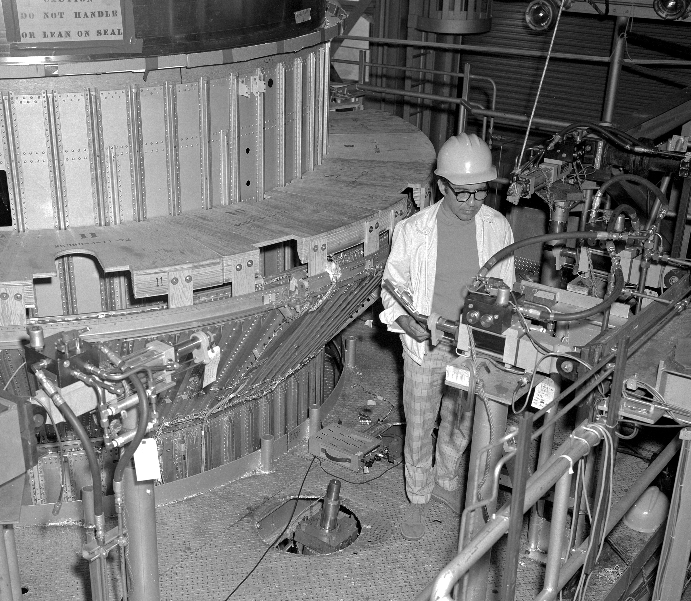
Tests: Researchers used the B–3 Stand for two extended test programs: the startup of the propellant flow system for the Kiwi-B nuclear engine and jettison tests of the CSS for the new Titan-Centaur vehicle. The B–3 tests established the proper startup procedure, which included liquid-hydrogen flow rates, power-cycle time delay, and the powering of the turbine. The B–3 Stand conducted a number of tests of the CSS for the new Titan-Centaur vehicle. Unlike previous B–1 or B–3 studies, these tests focused on the protective shroud, not the turbopumps. Unlatch tests verified that the CSS would jettison in a cold space environment, structural load tests determined the structural integrity of the CSS in a cold environment, and insulation tests led to a redesign of the insulation system.
- 1966 Kiwi-B engine propellant feed tests
- 1972–74 CSS jettison and tanking tests
Documents
- B-3 Floor Plans and Description
- B-3 Nuclear Rocket Flow Facility (1969)
- B-3 Stand Description (1974)
- B3 Stand Status Reports (1965-74)
- B-3 Historic Engineering Report Description
- B-3 Facility Resume (1960s)