Primary Test Cells
 Overview

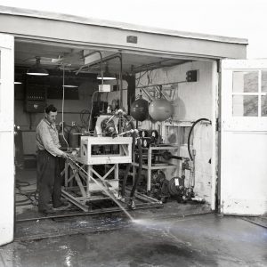
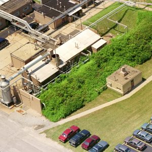
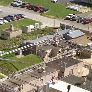
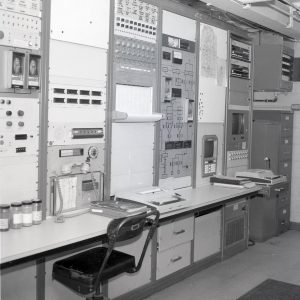
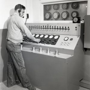
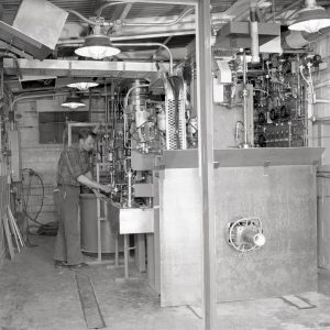
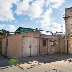
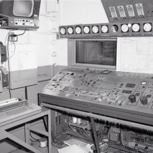
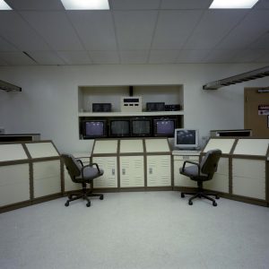
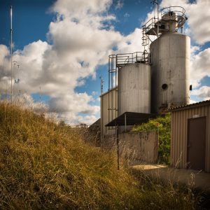
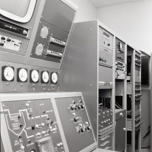
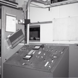
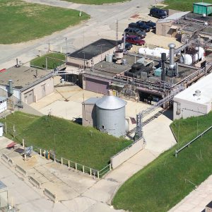
The Rocket Laboratory complex included ten test cells that were constructed in the 1940s and 1950s but were improved and modified over the years to meet changing test requirements. The individual cells were somewhat homogeneous physically, the installations and test equipment were unique. They were all supported by advanced data acquisition and control systems. The simple design of the buildings made them highly-adaptable to perform an array of testing. In addition, only a small operations crew was required to conduct most testing.
Documents
- Rocket Lab Facilities Manual (1991)
- Rocket Lab Overview (1992)
- Rocket Lab Test Cell Descriptions (1993)
- Rocket Lab Space Combustion Facilities (1994)
- Rocket Lab Fact Sheets (2000s)
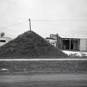
Original Test Cells
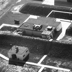
When it began operation in 1945, the Rocket Lab included four 20- by 8-foot test cells to conduct its testing. Cells 11 and 12 were located in Building 35—4 at the front, left area of the complex, while Cells 13 and 14 were in Building 35—5 to the right. Each of these single-story cinderblock buildings included the two test cells back-to-back facing opposite directions, two small control rooms, and a large service area. For the first few years of operation, Cell 11 was named Cell 4, Cell 12 was Cell 3, Cell 13 was Cell 2, and Cell 14 was Cell 1.
Cell 11
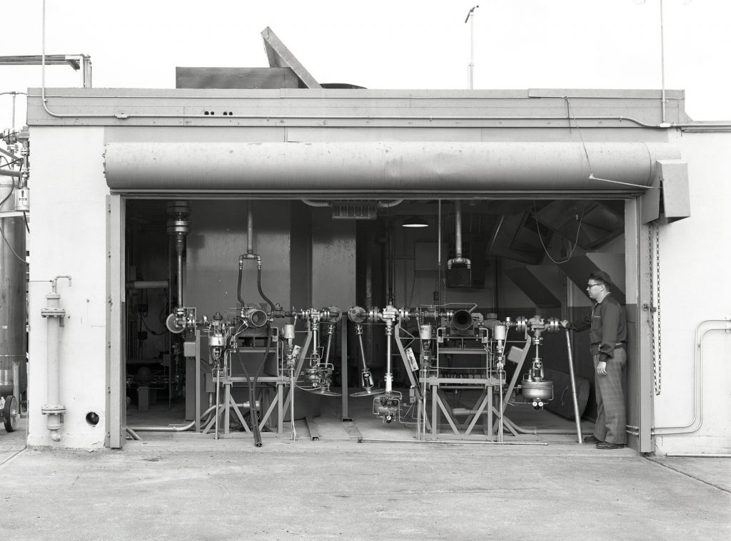
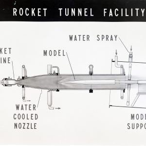
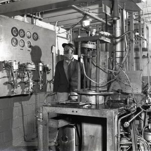
In the 1940s and early 1950s, Cell 11 contained a test stand for firing 100- and 500-pound-thrust liquid- fuel rocket engines aimed downward at a 45-degree angle for fuel evaluation and film cooling tests. In the mid-1950s, the cell was extended southward to accommodate a new 5,000 pound -thrust rocket-powered supersonic tunnel. The Rocket Tunnel simulated heating at hypersonic speeds. The cell appears to have been idle for a number of years until it was expanded in the late 1960s for testing of combustors for aircraft engines.
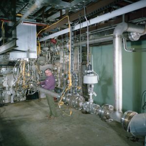
In the late 1970s, a flametube test rig was installed in Cell 11 to support combustion testing of coal-based fuels for the Department of Energy. In 1989, the Low Thrust Propulsion Facility was built for testing of gaseous hydrogen and gaseous oxygen thrusters in simulated altitudes. The upgraded test cell and control room could operate as an autonomous facility to expedite testing. Cell 11 underwent major construction in the early 1990s that included a large addition adjacent to the cell to house new laser measurement equipment.
Testing
- 1945-1946: Special fuels testing for U.S. Army Air Forces.
- 1946-1948: Fuel rating tests with 100 and 500-pound-thrust liquid-cooled transparent engines.
- 1949: Temperature survey of twin, parallel exhaust jets and engine film cooling.
- 1956-1958: Liquid hydrogen-liquid fluorine propellant combination.
- Heat transfer at supersonic speeds.
- 1969: Air-atomizing fuel injection, film cooling, and short-length combustors.
- 1979: Flametube studies for fuel control of fuel-bound nitrogen.
- 1983: Combustor flame flashback.
- 1991: Hydrogen film coolant injection in a hydrogen-oxygen rocket.
- 1991-1995: Hydrogen-oxygen thruster flowfields, nozzles, coated iridium-rhenium chambers.
- 1996: Electrolysis propulsion for spacecraft applications.
- 1997: Rocket-in-a-Duct performance analysis.
- 2013: Green Propellant Infusion Mission thruster testing, plume diagnostics, and technology maturation.
Documents
- Cell 11 and 12 Floor Plans
- Cell 11 Facility Outline (1988)
- Mach 4 Rocket-powered Supersonic Tunnel (1958)
- Combustor Flame Flashback Apparatus (1985)
- Low Thrust Rocket Test Facility (1990)
- Laser Rayleigh and Raman Diagnostics for Small Hydrogen/oxygen Rockets (1993)
Cell 12
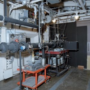
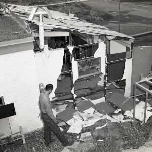
Cell 12 initially included test stands for testing small rocket engines both horizontally and at a 45-degree downward angle. The cell was used for film cooling investigations in the 1940s, then combustion vibrations in the 1950s. The cell was damaged by explosions several times during this period.
In the late 1960s, a test rig was built inside Cell 12 to study combustors with short diffusers. The setup included a pressurized system that supplied air flow to both the experimental combustors and ejectors, which provided a vacuum for the wall diffuser bleed flows.
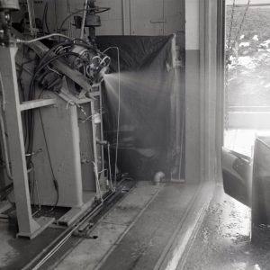
In the 1980s, a spray test rig was installed in Cell 12 to study multi-phased flow and fluid spray characterization. The system could measure spray droplets down to 5 micrometers. In the mid-1990s, a warm gas rig was built in the cell to support thruster testing.
Testing
- 1945-1946: Tests of Aerojet jet-assisted takeoff (JATO) rocket engine.
- 1946-1949: Water film cooling.
- 1949: Combustion vibrations in liquid engines.
- 1949-1952: Variable volume rocket combustion.
- 1956-1958: Screaming combustion with gas propellants.
- 1957: Drop size and scream.
- 1970-1971: Combustor diffuser testing and inlet flow control.
- 1986: Single nozzle testing.
- 1997: Monopropellant thruster testing.
Documents
Cell 13
In the 1940s and 1950s, Cell 13 was equipped to fire 1,000-pound -thrust rocket engines to conduct film cooling, combustion vibration, and other tests. In 1963, a 13- by 13-foot high bay was added to the southern end of Cell 13 to accommodate a pebble bed heater. The heater provided high-temperatures to simulate hypersonic flow.
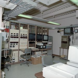
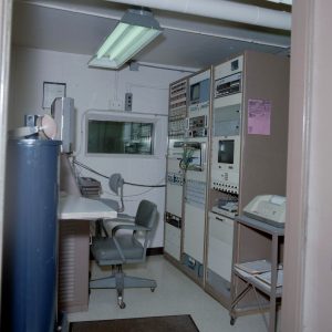
In 1973, Cell 13 was repurposed to test a Pressurized Fluidized Bed energy generation system. The experimental reactor was suspended inside the high bay. The modifications included the conversion of the joint Cell 13 and Cell 14 service area into a large control room. Cell 13’s original control room became a storage space for a 300-gallon dewar. The test equipment was modified again in the 1980s to support NASA’S Cryogenic Fluid Depot Program.
Testing
- 1945: Hydrogen peroxide film cooling.
- 1946: Nitric acid and aniline JATO rocket and high-speed pumps.
- 1946-1947: 1000-pound thrust liquid oxygen engine.
- 1947: Internal-film cooling of rocket nozzles.
- 1947-1949: Injection and combustion in variable volume rocket.
- 1949-1952: Combustion instability and screaming.
- 1950: Combustion instability in an acid-heptane rocket.
- 1954: Injection principles using liquid oxygen and heptane.
- 1956: Screaming in rocket motor.
- 1956-1958: Hydrocarbon fuels testing with fluorine.
- 1957: Injector size effects.
- 1958: Screaming in rockets.
- 1964-1967: High-temperature hydrogen nozzle testing.
- 1977-1980: Pressurized Fluidized-Bed Coal Program.
- 1990: Cryogenic fuel jet mixing.
Documents
Cell 14
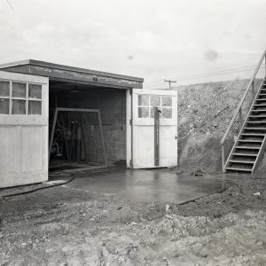
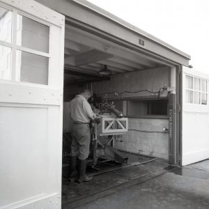
Cell 14 initially contained a test stand for 100-pound-thrust engines. The engines were pointed downward at a 30-degree angle to prevent accumulation of propellants in the combustion chamber at the start of runs. The stand could be pivoted horizontally. In the early 1950s, a storage area was added next to the control room and an awning was built over the test cell doorway.
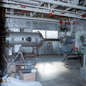
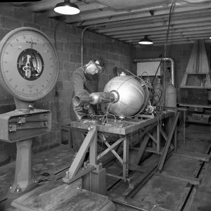
In the 1960s, the test cell doorway was sealed with a new wall and a spin test rig was installed for rotational testing of small engines. The test facility consisted of an air-driven turbine mounted in a vertical position on the top of a vacuum chamber, a dynamometer running at 1,440 revolutions per minute, and two step-up gear boxes.
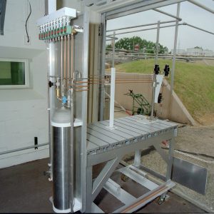
In the 1980s, Cell 14 was converted into a Metallized Rocket Propellant Flow Analysis Facility. The cell had multiple test rigs for testing metallized propellants to test feed systems, injectors, and tank expulsion.
Testing
- 1945-1946: Peroxide film cooling.
- 1947: 6000-pound thrust liquid cooled rocket.
- 1947-1951: Diborane with hydrogen peroxide, oxygen, and fluorine.
- 1953: Fluorine and ammonia combination in a 1000-pound-thrust engine.
- 1949-1950: High altitude, low temperature ignition of propellants.
- 1950-1952: Rocket engine film cooling.
- 1952: Combustion oscillation in rocket engine.
- 1955-1958: Hydrocarbon fuels with FLOX mixtures in a 1000-pound-thrust engine.
- 1958: Screaming in rocket engines.
- 1963: Design and cooling of a dump-cooled rocket.
- 1969-1972: Spin and magnetic testing of a welded rotor.
- 1977: Coal combustion testing.
- 1980s-1990s: Metallized propellant testing.
Documents
Second Generation Cells
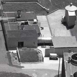
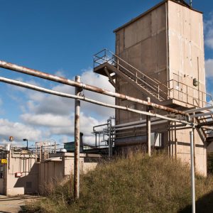
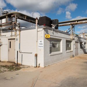
Four larger test cells (Cells 21—24) , 24- by 19-feet, were added in 1949. Cells 21 and 22 were in Building 35-7 at the left center, while Cells 23 and 24 were in Building 35—8 to the right. Each building included two parallel test cells with a shared control room between them and a large service area behind.
Cell 21
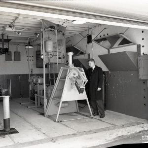
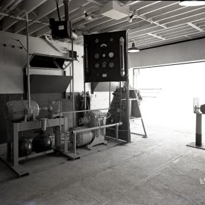
In the 1940s, Cell 21 contained a capsule in which 1,000-pound-thrust engines could be tested both at sea level and simulated altitudes. An ejector system used the rocket to reduce pressure within the capsule to simulate altitude. The exhaust was sent through a short horizontal tube before entering atmosphere. The capacity was increased to 5,000-pound-thrust in the mid-1950s. The stand was used through the 1960s to test various propellant mixtures and cooling systems.
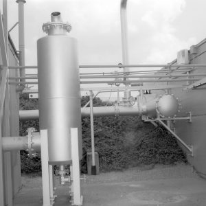
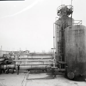
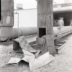
In the early 1950s, a second stand, 21B, was added to Cell 21. This Storable Propellant Test Facility consisted of the vertically mounted experimental engine that fired downward directly into a water-filled scrubber. The exhaust then flowed to a separate vertical exhaust stack that vented upward into the atmosphere. It was used to study ablative materials for nozzle throats.
In the mid-1980s, Cell 21 was overhauled to accommodate the Rocket Engine Ignition Test Facility. A new altitude exhaust system and gaseous hydrogen and oxygen supply systems were installed to permit the ignition studies of 50- to 100-pound-thrust engines at altitudes up to 90,000 feet. The setup, however, was primarily used for sea-level ignition tests. A laser equipment room was installed to support spray characterization and plume evaluations.
The equipment was replaced in the 1990s with a new installation for X-33 Combustion Wave Ignition testing. The test rig itself was located outdoors behind the cell. In 2001, a second test stand was added to Cell 21 to support the Pulse Detonation Engine Testbed. Both stands were capable of testing liquid and gaseous propellants.
Cell 21B
In the early 1950s, a second test setup (21B) was placed parallel to the original stand inside Cell 21 to study rocket engine screaming. It was modified in the mid-1960s to study flow water through experimental injectors in an 1,800-pound -thrust rocket. The installation was replaced by the Storable Propellant Test Facility, which consisted of the vertically mounted experimental engine that fired downward directly into a water-filled scrubber. The exhaust then flowed to a separate vertical exhaust stack that vented upward into the atmosphere.
In the early 1970s, a new 3,000-pound-thrust test stand was installed to operate small, horizontally- fired thrusters. The attachment of a graphite exhaust diffuser to the stand permitted altitude simulation. Stand 21B, which appears to have last been used for roller drive testing in the 1970s, was subsequently removed from the facility.
Testing
- 1949-1952: Fuel injection and combustion tests, spiral engine.
- 1952: Screaming in rocket chamber (21B).
- 1956: Altitude performance of a JP-4 and oxygen engine.
- 1961: Hydrogen-fluorine performance and ignition.
- 1964-1967: Injector flow tests with water (21B).
- 1964-1968: Ablative materials for nozzles throat inserts.
- 1968: Oxidant-fuel-ratio-zoned injector (21B).
- 1972: Hydrogen-oxygen attitude-control thruster (21B).
- 1977: Traction drive for a cryogenic boost pump (21B).
- 1978-1981: Catalytic Combustor Rig.
- 1983-1984: Cold flow swirl experiment.
- 1984: Spray characteristics of an airblast atomizer.
- 1984-1986: Single nozzle testing.
- 1987: Catalytic ignition of hydrogen and oxygen propellants.
- 1989-1995: Carbon monoxide and oxygen ignition and heat transfer.
- 1989-1994: Ignition and combustion of metallized propellants.
- 2005: Metallized gelled propellants in a pulse engine.
- 2006: Hydrogen fuel system for high-altitude aircraft.
- 2008: Liquid oxygen-methane glow plug igniter tests.
Documents
- Cells 21 and 22 Floor Plans (1956-2000)
- Cell 21 Facility Outline (1988)
- Low Thrust Rocket Facility Description (1993)
- New Test Stands for Cells 21 and 22 (2002)
Cell 22
Cell 22 was the laboratory’s primary rocket engine and propellants testing facility throughout the 1950s.
It contained two parallel test stands capable of firing 5,000-pound-thrust engines. The engine was mounted horizontally on a test bed that was suspended from the thrust stand frame. A transducer on the combustion chamber measured thrust, and a transducer mounted between the thrust stand and a post provided calibration. A large scrubber was constructed behind the test cell in 1955 to remove contaminants from the engine exhaust. In the mid-1960s, Cell 22 was used to test injectors and ablative materials for combustion chambers.
In 1973, Cell 22 was overhauled to support testing of magnetohydrodynamic rockets. The cell was renovated again in the early 1980s to test various materials performance in a gaseous hydrogen and oxygen high-heat-flux environment. This High Heat Thermal Shock Facility simulated the high temperature, high pressure, gas velocity, thermal shock, and thermal gradient environment experienced by hypersonic engines. Cell 22 was subsequently used to test ceramic composites, transpiration-cooled seals, thin film thermocouples, and leading edge erosion and oxidation.
Prior to its demolition, many of the Cell 22 capabilities were transferred to Cell 32.
Testing
- 1954: Regenerative cooling in a 5000-pound-thrust liquid oxygen and JP-4 engine.
- 1954: Liquid hydrogen and liquid oxygen in a 5000-pound-thrust engine.
- 1956: Fluorine-ammonia in Roe engine; Jet fuel and FLOX combination.
- 1957: Fluorine-ammonia, liquid hydrogen-liquid oxygen, liquid hydrogen- liquid fluorine, and hydrocarbons and liquid oxygen propellant combinations.
- 1957: Performance of a hydrogen and fluorine regeneratively-cooled engine.
- 1958: Experimental performance of a hydrogen and fluorine rocket engine.
- 1960: Injectors for hydrogen and fluorine engines.
- 1964-1968: njectors and ablative chambers for a FLOX and propane engine.
- 1968: Testing of a 1000-pound-thrust FLOX and propane ablative engine.
- 1974: Hydrogen-Oxygen Magnetohydrodynamic Program.
- 1977: Temperature distributions of cesium-seeded hydrogen-oxygen free jet.
- 1985-1992: Hypersonic engine components in a high-heat-flux environment.
- 1995: Ablative material testing for low-cost rocket engines.
- 2000: Flow field of thruster having attached panel.
- 2005: GRCop-84 rocket thrust chambers.
- 2009: Integrated High Payoff Rocket Propulsion SiC Recession Model.
Documents
- Cell 22 Facility Outline (1988)
- A Versatile Rocket Engine Hot Gas Facility (1993)
- Combustion Research Facility for Testing Advanced Materials (2003)
- Characterizing the Chemical Stability of High Temperature Materials (2005)
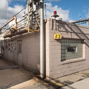
Cell 23
In the 1950s, Cell 23 had two test setups, Rig 23A and Rig 23B, which fired towards the ground. 23A was used to test injectors on a 1,500-pound-thrust engine, and 23B consisted of a 1,000-pound-thrust rocket with transparent plastic combustion chamber section to study rocket screaming. In 1962, a silo-like structure (Cell 23D) was built behind Cell 23 for testing involving a large liquid hydrogen tank.
In 1980, a new 2,700 degree Fahrenheit transient combustor rig was installed in Cell 23 to test ultra-low-emission combustors. This rig, referred to as the Hydrocarbon Fuel Combustion Test Rig, was designed to burn fuels in pre-heated air to determine fuel performance and emission levels. It was used to test fuel-rich, catalytic reaction systems.
In early 1990s, Cell 23 converted into flametube rig with a 3-inch square flow path to provide initial evaluation fuel injectors designs before their testing in larger, more expensive facilities. In the early 2000s, a new gaseous hydrogen supply and control system were installed in Cell 23 to improve the low-emission combustor testing—allowing test of combustors with zero carbon dioxide emissions. The hardware interface was replaced by a digital system.
Testing
- 1949-1950: High-energy rocket propellants.
- 1950-1951: Combustion vibrations in rockets.
- 1951-1953: Photographic study of rotary screaming.
- 1957: Liquid oxygen, JP-4, and kerosene in a rocket.
- 1959: Evaluation of rocket exhaust diffusers with various nozzles.
- 1974: Centaur boost pump test.
- 1981: Combustion characteristics of gas turbine alternative fuels.
- 1985 -1986: Gas turbine alternative fuels combustion.
- 1991: Fuel-rich, catalytic reaction experiment.
- 1996: Teledyne Ryan Ultra Lean Combustor.
- 2004: Low emission hydrogen combustors using lean direct injection.
Documents
- Cells 23 and 24 Floor Plans (1956-2000)
- Cell 23 Facility Outline (1988)
- Cell 23 Combuster Test Facilities (1995)
- RL-23 Combustor Test Facility (1995)
- Fuel-Flexible Gas Turbine Combustor Flametube Facility (2004)
Cell 24
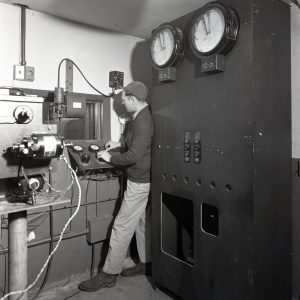
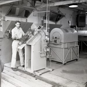
Cell 24 originally contained equipment for ignition testing of small- and intermediate-sized rocket engines. The setup included a transparent combustion chamber, propellant tanks, a gas pressure supply reservoir, a photographic system for ignition-delay measurement, means for obtaining and controlling propellant temperature and initial ambient pressure, and instrumentation for indicating and recording combustion-chamber pressure and other operating variables. It was briefly used in the late 1950s to study rocket screaming. In 1959, it was set up to test small reaction control thrusters.
Testing
- 1951: Ignition delay with a small-scale rocket at simulated altitude
- 1952: Ignition delays of propellant combinations in a 50-pound-thrust engine.
- 1952: Engine starting with nitrogen and ammonia oxides.
- 1954: Performance of FLOX and JP-4 in a rocket engine.
- 1955: Chemical igniters and ignition delay tests (Rig A).
- 1956: Low temperature starting.
- 1957: Ignition lag of self-igniting fuel-nitric acid.
- 1957: Liquid oxygen and heptane propellant combination.
- 1957-1958: Geometry and screaming in rockets.
- 1967: Fuel deposits study.
- 1977: Burning Rate Rig.
- 1981: Flametube combustor testing.
Documents
Cell 24B
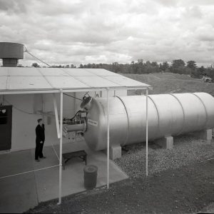
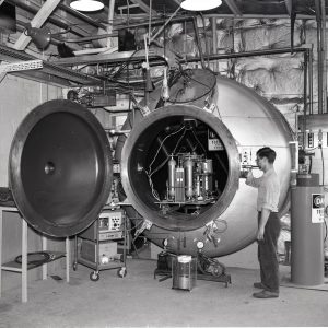
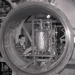
In 1949, a 29-foot long and 8-foot diameter cylindrical tank was installed outside Cell 24 to allow altitude testing of engines. The engines were mounted in a cold bath to simulate temperatures at altitude. The Cell 24B setup was supported by a purge blower and vacuum pump located inside the main Cell 24 area. The area at the front of the tank, later referred to as Cell 24B, was initially sheltered with an awning before a roof and walls were constructed.
The structure was improved in the early 1970s and given a permanent roof. The long tank was removed from the facility in 1981 so that large rolling element bearings for turbopumps could be tested. The rig could subject bearings to speeds up to 2500 revolutions per minute and large thrust and radial loads.
Testing
- 1949: Starting of rocket engine in simulated altitude conditions.
- 1952: Chemical starting technique for acid and gasoline rocket.
- 1954: Low temperature starting of 200-pound-thrust JP-4 and nitric acid engine.
- 1957: Altitude starting of a 1000-pound-thrust solid rocket.
- 1959: Effect of temperatures on hydrogen peroxide thrusters.
- 1965: Performance of bipropellant fractional-pound thrusters.
- 1967: Performance of a water-electrolysis rocket.
- 1970: Hydrazine rocket thruster.