Conducting a Test

This page describes the basic theory of rocket propulsion and the steps necessary to test an engine at the Rocket Engine Test Facility (RETF). This theoretical engine test uses liquid hydrogen as the fuel and liquid oxygen as the oxidizer.
Rocket Propulsion 101
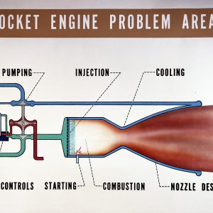
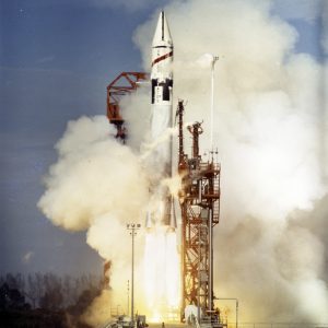
Thrust is the force that moves a rocket through the air. A rocket’s propulsion system generates thrust using Newton’s third law of motion—for every action there is an equal and opposite reaction. In this theoretical test, a selected fuel and an oxidizer are pumped into a combustion chamber where they are mixed and burned. The combustion produces great amounts of high-temperature, high-pressure exhaust gas. The hot exhaust is passed through a nozzle that accelerates the flow (action). Thrust is produced in the opposite direction (reaction). The amount of thrust depends on the exit velocity from the nozzle and on the mass flow rate through the nozzle.
The amount of thrust can be modified by changing the fuel type, the pump output, or the nozzle shape. The selection of the rocket propellants (fuel and oxidizer) determines the mass of the exhaust gas and the energy that can be derived from the fuel. The selection of the fuel, combined with the oxidizer, affects the amount of thrust produced by the rocket engine. The pumps force the fuel and oxidizer into the igniter and combustion chamber at a predetermined rate. The flow rate set by the pumps affects the amount of thrust produced by the rocket engine.
The nozzle converts the energy into exhaust velocity, and the exhaust velocity affects the amount of thrust produced by the rocket engine. A nozzle with a large area ratio from the exit of the nozzle to the throat of the nozzle produces a large exhaust velocity.
Documents

Setting Up the Test Site
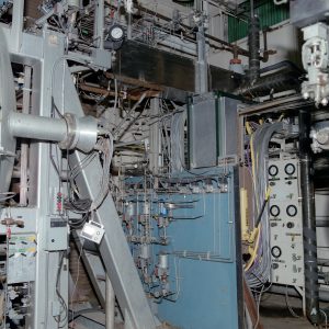
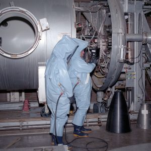
A great deal of attention went into preparing the RETF to achieve the best results during rocket testing. Precision and accuracy were crucial. Test runs required specially designed equipment and sensitive instruments, and researchers had to follow standardized procedures.
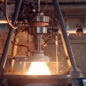
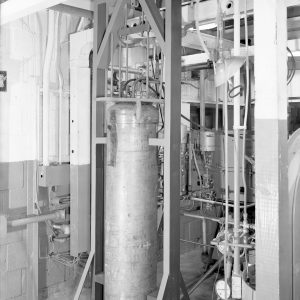
The RETF test programs often used relatively inexpensive subscale engines made of carbon steel coated with a ceramic coating known to the trade as “Rockide.” These engines could be reused for several cycles of testing. When the Rockide coating became thin, the engines were recoated and put back into the test program. The hardware designers found they could obtain useful test data without employing expensive water cooling systems by firing the Rockide-coated steel engines for periods as short as three seconds.
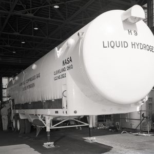
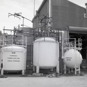
Liquid hydrogen was pumped from a mobile tanker trailer into the cylindrical tanks in the fuel pit area. These tanks were mounted in a special framework that contained sensors (load cells) that measured the weight of the tanks.By comparing the weight of a full tank with the weight of the tank after a test, researchers could accurately determine the amount of fuel burned during the test. The engineers could then calculate the rate of fuel use by plotting the weight of the tank against the time length of the test.
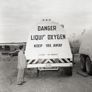
When liquid oxygen was used as the oxidizer, it was transferred from a mobile tanker trailer through a pipe into a tank in the oxidizer pit. Special equipment was needed to keep the oxygen in a liquid state as it traveled through the pipe and was stored in the tank. Each tank, called a “dewar” was vacuum insulated and double walled. A liquid-nitrogen bath was circulated between the two walls of the tank to keep the oxygen cool and in its liquid form. The pipe to the tank also had an outer covering that contained a liquid-nitrogen bath.
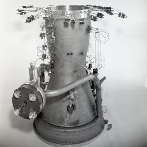
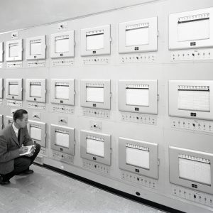
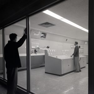
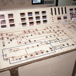
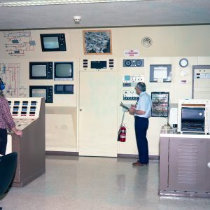
To gather data from the experiments, researchers used numerous sensors on the engines, such as load cells, strain gages, thermocouples, and pressure gages. The wires from the sensors were connected to terminal blocks and amplifiers in the terminal room of the Rocket Engine Test Cell. Because the magnitude of some of the electrical signals was quite small, the signals needed to be amplified before they were transmitted to the control room. Once amplified, the electrical signals were transmitted over data transmission cables to the readout devices in the control room in Rocket Operations Building,around 1,600 feet away.
Great care was taken to make sure that the test was completed with the utmost safety. RETF had a number of different systems to help warn people to stay away from the site during a test. Signs and barriers were positioned around the perimeter of the test facility. Green, yellow, and red were used to indicate different alert levels. The facility had a public address system that was used to warn workers in the surrounding areas of testing, and sirens were sounded 30 seconds before a rocket firing and continued until the test was complete.
Running the Test
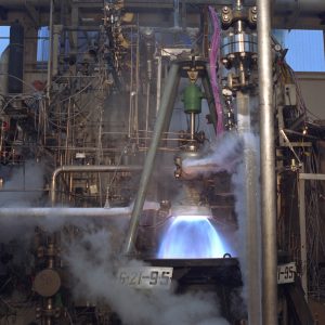
Once the test site was prepared and safety precautions completed, it was time to run the test. Procedures were divided into carefully choreographed periods called “zones” to accomplish specific tasks. During the pretest zone, engineers pressurized and test fired the igniter system, chilled the liquid hydrogen line leading into the injector with liquid helium, and pressurized the propellant tanks.
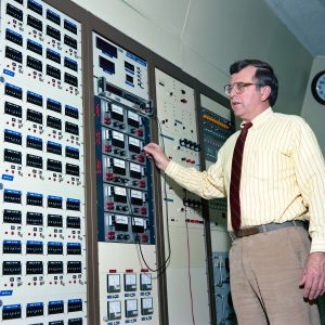
The test engineer-in-charge then pushed the start button to begin the test. During the first 15 seconds the data systems automatically calibrated the instruments and started recording pressure and temperature data on strip charts; and the gaseous nitrogen used to purge the propellant lines and water started to flow into the scrubber. After 11 seconds, a two-second flow of oxygen began in order to cool the engine, and at 13 seconds, gaseous-nitrogen purges cleared the engine of liquid oxygen.
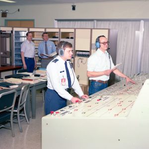
The most critical time was this next three-to-five-second period, when the test engineer-in-charge turned on the igniter and checked the pressure of the combustion chamber. Two propellant fire valves automatically opened, allowing liquid hydrogen to flow into the rocket engine. After 450 milliseconds, propellant and combustion chamber pressures were checked. If they were within limits, the test continued, though the test conductor kept his hand near the abort button. After 2.5 seconds had lapsed, the fire valves were closed and the engine was shut down.The propellants were flushed from the lines beyond the fire valves, the purges were restarted, and finally, test shutdown initiated.
In the final 120 seconds of the test, the engineers completed the engine shutdown. They then rendered the area safe for inspection, took calibrations again, turned off the scrubber, and turned off all data systems.
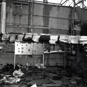
At any time during a test, if the engineers monitoring data in the control room noted abnormal propellant and chamber pressures, the engineer-in-charge could immediately abort the test by pressing the abort button. However, it was more likely that the computers would sense a problem and automatically shut down the test. During an aborted procedure, propellant fire valves automatically slammed shut. The shut-off valves on the two propellant tanks also automatically closed, and the prime vent valves, which were located in the line between the tank shut-off valves and the fire valves, opened to vent any propellants trapped in the line. Slamming shut the tank valvesprevented propellants from escaping into the test facility itself, a potentially dangerous event that could allow unburned propellants to explode. When explosions did occur, a full investigation was carried out to determine the causes before they resumed any testing.