SPC Facility Description
In the early 1960s, NASA converted the AWT into two large altitude test tanks known as the Space Power Chambers (SPC).
Overview
After becoming part of the new National Aeronautics and Space Administration (NASA) in the fall of 1958, the Lewis Research Center shifted nearly all of its resources to space-related research. This dramatically reduced the need for the Altitude Wind Tunnel (AWT) and other aeronautics-based facilities. Management decided to repurpose the facility by constructing two large chambers capable of simulating altitudes. This required the removal of the tunnel’s drive fan, exhaust scoop, and turning vanes from the east end and the insertion of bulkheads to seal off the new chambers within the tunnel. The eastern section of the tunnel, SPC No. 1, became a vacuum chamber capable of simulating 100 miles altitude. The larger SPC No. 2 in the western leg of the tunnel could simulate altitudes of 100,000 feet. These chambers were used for a variety of tests on the Centaur second-stage rocket until the early 1970s.
Documents
- Overview of SPC Environmental Tests (2009)
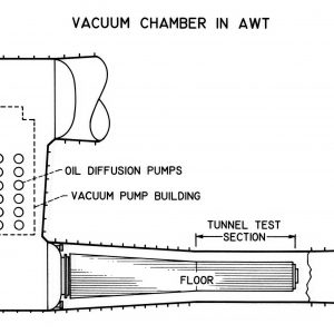
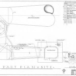
- SPC Facility Layout Drawing
- SPC Complex Description (1975)
- SPC Historic American Engineering Report (2009)
Space Power Chamber No. 1
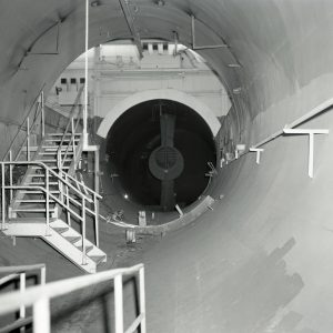
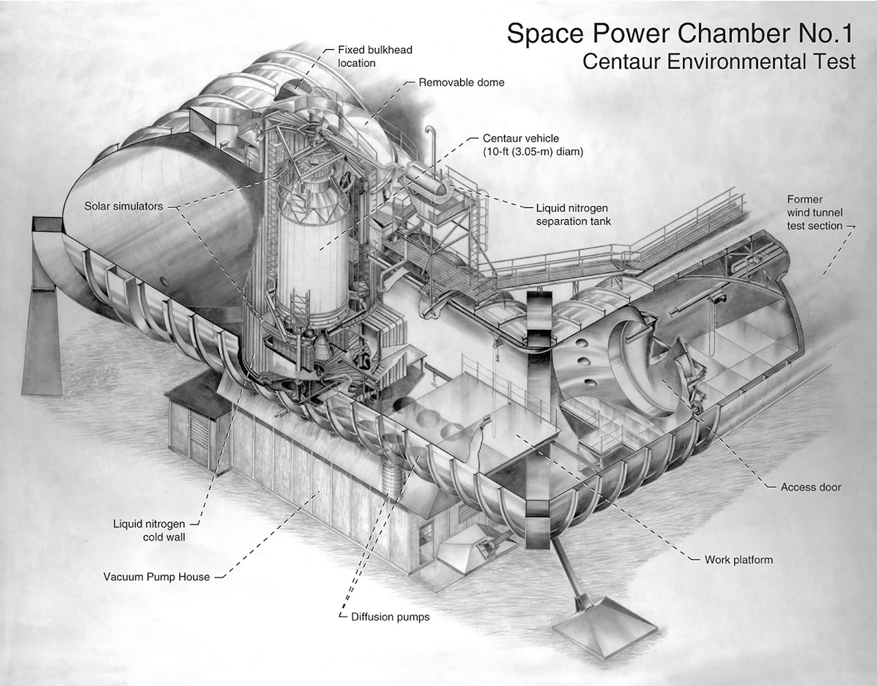
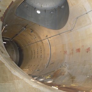
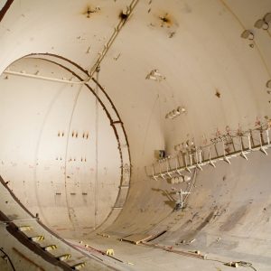
The 100-foot-long SPC No. 1 was located in the east leg of the tunnel, which was 31 feet in diameter at one end and 27 feet in diameter at the other. It was necessary to reweld the 1-inch-thick chamber shell during the conversion in order to maintain the low pressures necessary to simulate the space environment. The insulation and outer weather shield were permanently removed from this section at that time. The chamber was segregated from the rest of the tunnel by bulkheads at the southwest and northwest sections. Access to the chamber was provided by a 15-foot diameter door in the latter. SPC No. 1 included an overhead rail crane, various instrumentation ports, and numerous fixed eyehooks and other fittings that were used for various test setups.
A small vacuum pump house was built beneath SPC No. 1 to accommodate the ten diffusion pumps and several roughing pumps necessary to create a deep vacuum. Access ports in the chamber’s floor connected directly to the pumps in the building below. The vacuum was brought down slowly in several phases to prevent excessive airflow over the pumps. The center’s central exhauster system could evacuate the SPC to 100,000 feet pressure altitude in about 15 minutes. Then, two piston pumps simultaneously removed 12.5 cubic feet of air per second during the roughing stage. A rotary positive displacement pump pulls additional air at 500 cubic feet per second. The final vacuum is pulled down by the ten 32-inch-diameter oil diffusion pumps, which could remove 17,650 cubic feet air per second.
Modifications for Centaur
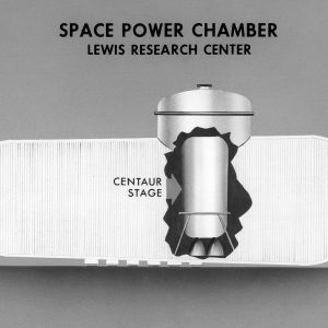
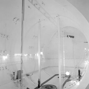
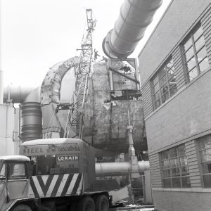
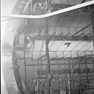
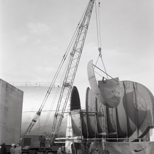
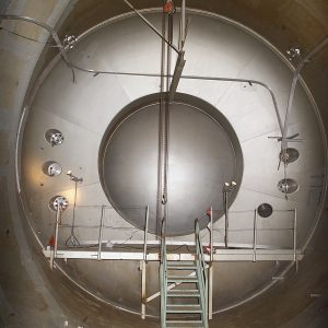
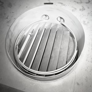
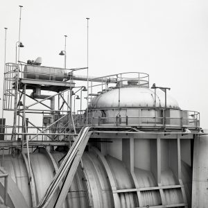
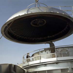
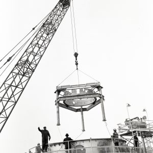
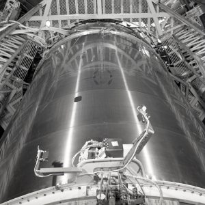
NASA intended to use the SPC No. 1 vacuum tank to test satellites, space power systems, and small space vehicles. In the fall of 1962, however, Lewis assumed responsibility for the Centaur upper-stage rocket. Lewis management decided to modify SPC No. 1 to accommodate the stage. A vertical 17.5-foot extension with a removable cap was added to the top of the chamber so that a Centaur could be placed vertically within the tank. The 22.5-foot-diameter lid could be removed using a crane so that the Centaur or other test articles could be lowered into the chamber. An elevated catwalk was erected around the dome to allow access to the instrumentation portals and cable trays.
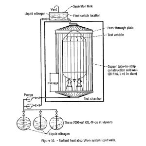
SPC No. 1 was already capable of creating the vacuum of space, but the test engineers also wanted to simulate the cryogenic temperatures and solar radiation found in space. A 42-foot-high copper cold wall was created specifically for these tests and assembled around the Centaur. Cryogenic liquid nitrogen flowed through vertical ribs in the wall and the shroud’s interior was coated with heat-absorbing black paint to generate the low temperatures. In addition, six panels of 500-watt tungsten-iodine lamps were arranged around the Centaur to simulate the effect of the Sun’s heat on the rocket performance. Four of these arrays were on the upper end of the Centaur, and two were located near the RL–10 engines. Certain lamps could be turned on at different times to recreate the changing areas of the rocket exposed to sunlight during a mission.
The actual setup of the Centaur included a pneumatic system to keep the vehicle’s thin fuel tanks pressurized so that they would not collapse, a hydraulic system to rotate or “gimbal” the engines as they would be during flight, and a liquid-hydrogen pumping system to fill the propellant tank. The telemetry for these tests included a high-powered system for powered flight, a lower power system for coast periods, camera and data transmission systems to view the liquid hydrogen tank, ground support equipment that controlled and monitored the operation of the Centaur, and extensive instrumentation.
Space Power Chamber No. 2
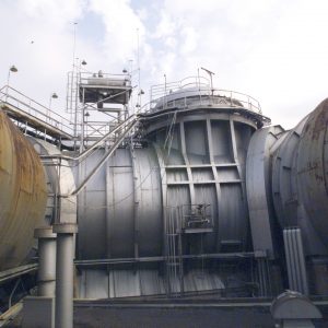
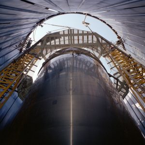
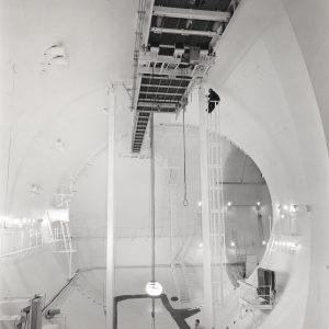
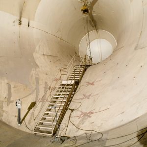
SPC No. 2 was the larger of the two chambers in the former AWT. It consisted of the entire southern and western legs of the tunnel, as well as the throat section. SPC No. 2 was sealed off from the other chamber by a 31-foot bulkhead near the southeast corner and from the tunnel test section by a 20-foot-diameter bulkhead in throat section, which effectively made SPC No. 2 a large J-shaped chamber. The 51-foot-high chamber in the west leg allowed the vertical erection of full-scale rocket shrouds so that the jettison systems could be tested at high altitudes.
Unlike the vacuum tank in SPC No. 1, SPC No. 2 did not require a major overhaul to be used as a high-altitude test chamber. The existing AWT exhauster and refrigeration systems were powerful enough to achieve the desired altitudes up to 100,000 feet. During the conversion to the SPC, this chamber only required the two bulkheads that sealed it off, some upgraded crane equipment, and a new coat of paint.
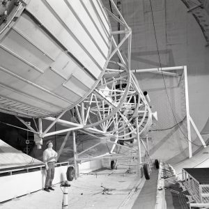
In order to work on the tall shrouds, an oval platform elevator was built on two vertical steel girders. The elevator could be raised the entire length of the chamber, and its 11-foot-diameter opening allowed it to be placed around payload shrouds to assist in test preparations. The catwalk along the western wall provided access to lighting and cameras used to record the tests. An overhead crane was installed over the chamber to permit the transfer of large test articles.
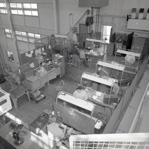
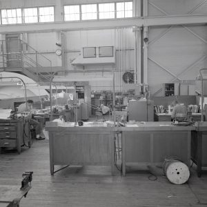
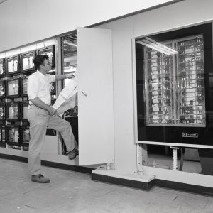
Control Rooms
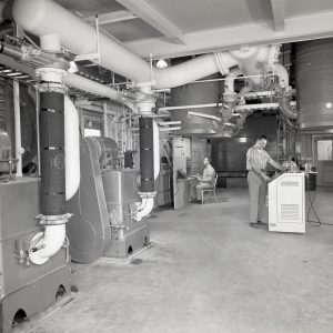
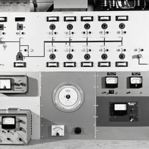
The SPC had separate control rooms for each of its two test chambers. The former AWT control room next to the test section was used for the tests in SPC No. 2. The conversion primarily involved rewiring the telemetry and updating the control panels. The floor-mounted pneumatic engine controls were also removed. The original acoustic tiles on the walls and ceiling remained, as did the overhead fluorescent light fixtures. The eastern panel, which had the system laid out schematically on the panel with toggle switches and indicator lights, controlled the exhaust flow. The next panel operated the liquid nitrogen system. The panel at the west end contained a large number of controls for cameras inside SPC No. 2.
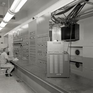
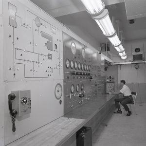
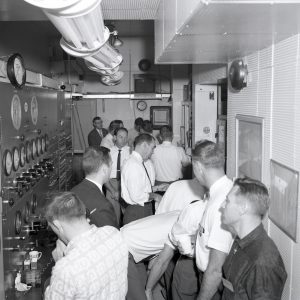
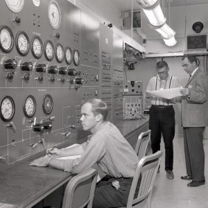
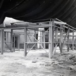
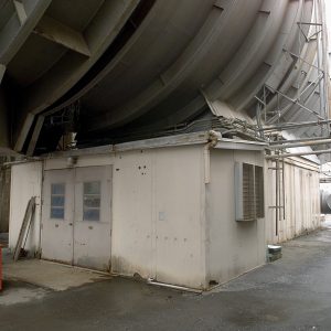
A new control room for SPC No. 1 was constructed underneath the former tunnel’s test section. Efforts were made to make this control room as much like the Centaur launch controls at Cape Canaveral as possible. The eastern wall contained the primary controls, including Centaur pressure and tanking controls; hydrogen peroxide, hydraulic, stretch, pneumatic, and canister purge systems; the cold wall and vacuum systems, and solar simulator temperature monitor. The northern section consisted of monitors for temperature, pressure, and the solar simulator. The western wall controlled the guidance system, nose cone, and tank vents. The southern section had data and event recorders as well as radio frequency and range safety monitors. Racks in the center of the room contained the test conductor and engine controls, ground programmer, a vehicle power monitor, and data recorders.
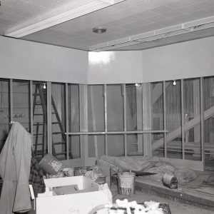
Since the tunnel’s test section no longer needed to be enclosed, the large clamshell lid was removed. Flat, steel grating was installed in the bottom of the test section and a pedestrian bridge was built over the 20-foot-wide gap. A new rail crane was installed in the tunnel between the test section and bulkhead so the test articles could be transported into SPC No. 1. The surrounding test chamber room was used as a work area for mechanics in the 1960s and storage area in recent years.