Combustor Facilities
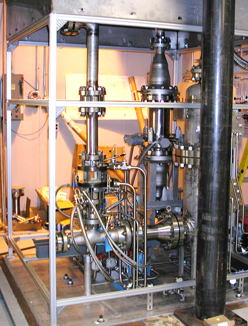
Sector Combustor Studies (CE-5B-1)
Combustion studies are conducted in this two-test position facility specifically in support of the NOx reduction research for the HSR program and the AST program. CE-5B-1 is large enough to test sector arrangements of injector elements, to include interactions of the elements, and single larger elements. The facility receives filtered combustion air from the 450 psig system. The air is heated in a 1100 deg F non-vitiated heater at flows up to 20 lb/s, which can be valved to either test stand. The airflow passes through the test section, is water spray quenched and then discharged to the altitude exhaust system or the atmospheric exhaust system. The facility preheater consists of a heat exchanger fired by four J-47 burner cans using natural gas for a fuel and the 40 psig combustion air. The research hardware uses ASTM Jet-A, JP-5, or JP-8 as a fuel.
CE-5B-1 Special Features
In addition to inlet and exit rakes and standard instrumentation, water-cooled gas sampling rakes are in the downstream section. Particulate measurements are taken at the exit of the combustion section. Optical accessibility of the combustor section allows never before possible nonintrusive laser-based diagnostics of the reacting and non-reacting flowfield. These include such techniques as planar laser-induced fluorescence (PLIF) imaging, Planar Mie scattering, Phase/Doppler particle analysis (PDPA), focused Schlieren imaging and light sheet photography. Both rigs share the gas analysis, particulate analysis, and diagnostics equipment.
| Parameter | Operating Value |
|---|---|
| Inlet air supply pressure | 450 psig |
| Inlet air temperature | 100°F, preheated to 350-1350°F |
| Inlet airflowStand 1Stand 2 | 20 lb/s (available) 0.5 to 12.0 pps 0.5 to 5.0 pps |
| Exhaust | Atm or 20-26 in. Hg |
| Rig pressure without windowsStand 1Stand 2 | 275 psig 400 psig |
| Rig pressure with windowsStand 1Stand 2 | 250 psig 275 psig |
| Rig Fuel (JP-8) flow | 7 gpm @ 400-900 psig (three legs per stand) |
| Window cooling GN2 (4 legs) | 0.125 to 0.5 pps (each leg) |
| Cooling water | 150 gpm @ 460 psig 250 gpm @ 395 psig 50 gpm @ 350 psig 15 gpm @ 55 psig |
| System | Number and Type |
|---|---|
| ESP | 96 Ports of + 500 PSID Barometric Ref |
| Escort | 240 Channels 154 Available to the Customer |
| Thermocouples | 156 Type K 24 Type B 12 Type W 524 Type R |
| Gas Analyzers | HC – 1000 ppm 1% & 5% CO – 2000 ppm 5% CO2 – 5%, 10%, 20% O2 – 25% NO – 100 ppm, 1000 ppm 1% NOx – |
| Laser | PLIF, Raman |
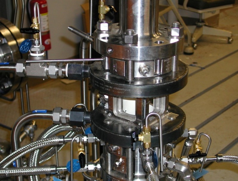
Flametube Combustor Studies (CE-5B-2)
CE-5B-2 is one of the two test stands in the CE-5B facility and can be configured to study lean-premixed-prevaporized (LPP) and Lean-direct-injection (LDI) concepts for developing a low NOx combustor for high speed research and advanced subsonic applications. The non-windowed combustion flametube can use a three inch square cross-section or a three inch diameter round section and has six ports available for gas sampling probes. The windowed combustion flametube takes advantage of the flat walls on a three inch square cross-section to install optical windows for non-intrusive measurements. Tests are conducted with combustion air inlet pressure ranging from 10 to 15 atmospheres with preheater and exhaust conditions described for CE-5B-1.
CE-5B-2 Special Features
The same laser based non- intrusive diagnostics of reacting and non-reacting flowfields described for test position CE-5B-1 are available to this test section. A typical data acquisition system, is used for both test positions in CE-5B; in addition, most of the optical diagnostic instruments have their own data acquisition systems.
| Parameter | Operating Value |
|---|---|
| Inlet air supply pressure | 450 psig |
| Inlet air temperature | 100°F, preheated to 350-1350°F |
| Inlet airflowStand 1Stand 2 | 20 lb/s (available) 0.5 to 12.0 pps 0.5 to 5.0 pps |
| Exhaust | Atm or 20-26 in. Hg |
| Rig pressure without windowsStand 1Stand 2 | 275 psig400 psig |
| Rig pressure with windowsStand 1Stand 2 | 250 psig275 psig |
| Rig Fuel (JP-8) flow | 7 gpm @ 400-900 psig(three legs per stand) |
| Window cooling GN2 (4 legs) | 0.125 to 0.5 pps (each leg) |
| Cooling water | 150 gpm @ 460 psig 250 gpm @ 395 psig 50 gpm @ 350 psig 15 gpm @ 55 psig |
| System | Number and Type |
|---|---|
| ESP | 96 Ports of + 500 PSID Barometric Ref |
| Escort | 240 Channels 154 Available to the Customer |
| Thermocouples | 148 Type K 24 Type B 48 Type R |
| Gas Analyzers | HC – 1000 ppm 1% & 5% CO – 2000 ppm 5% CO2 – 5%, 10%, 20% O2 – 25% NO – 100 ppm, 1000 ppm 1%NOx – |
| Laser | PLIF, Raman |
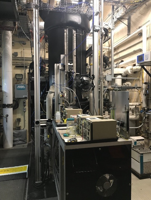
Combustion and Dynamics Facility (CE-13C)
Test Cell CE-13 Combustion and Dynamics Facility (CDF) is used to investigate ways to reduce NOx and particulate emissions from air-breathing aircraft engines. This low pressure (1 – 5 atm) facility is used to study fuel-air injection schemes and how they affect fluid mixing, emissions, dynamics, and flame stability. Jet-A fuel is the primary fuel, but candidate alternate jet fuels and their effects are also studied. Standard measurements consist of major species and dynamic pressures. Some optical measurements available are high speed video, standard and time-resolved 2D PIV, planar laser induced fluorescence (PLIF), and chemiluminescence imaging.
CE-13C Special Features
Research hardware is designed to flow vertically downwards. Preheated air is fed to the inlet air stream conditioner and then to the fuel injector. Fuel at room temperature is fed separately to the injector. The mixed hot air and fuel mixture moves to the combustor where combustion can be observed via customized windows. The products of combustion flow through an emission sampling ring, and choke nozzle/straight outlet pipe. The fuel system consists of a 25-gallon fuel tank, a pump and GN2 purge. A separate laser room operates various class 3B and 4 lasers (UV, Vis, NIR) to characterize fuel injection, combustor flow, and measure combustion species.
| Parameter | Operating Value |
|---|---|
| Inlet air pressure | Ambient to 75-psia |
| Inlet air temperature | Ambient to 1000°F |
| Inlet air flow | 0.0 – 1.0 pps |
| Jet fuel supply | CKT 1 6.9-140 pph @ 1000-psig CKT 2 1 – 13.1 pph @ 1000-psig |
| Exhaust | Atmospheric |
| Peripheral H2O Cooling | 54-gpm @ 100-pisg |
| Quench cooling | 11-gpm @ 500-psig |
| System | Number and Type |
|---|---|
| Labview | 64 voltage/current channels
32 temperature channels 10 voltage/current channels Available to the Customer 30 temperature channels available to customer |
| Optical and Laser | PLIF, Raman, PIV, droplet sizing, chemiluminescence, temperature, time-resolved imaging |
| Gas Analyzers | CO – 1000 ppm, 5000 ppm
CO2 – 5%, 15% O2 – 25% NO – 100 ppm, 1000 ppm NOx – 100 ppm, 1000 ppm HC – 100 ppm, 1000 ppm |
High Pressure Gaseous Burner (SE-5)
The SE-5 High-Pressure Combustion Diagnostics (HPCD) laboratory is a gas- and liquid-fueled high-pressure flame tube facility with single-element fuel injection burner(s) and emission sampling ports for advanced diagnostics development and national standard calibrations. The facility provides large-aperture optical access to the primary reaction zone (flame holding) through four UV-grade fused silica optical windows (44-mm thick by 85-mm clear apertures located around the periphery), enabling non-intrusive optical diagnostics such as laser Raman spectroscopy or high-speed imaging to measure chemical species and temperature. The HPCD rig can operate at sustained pressures up to 30 atm (or 60 atm with limited flow rate) with a variety of gaseous fuels, liquid jet fuels, and oxidizers, including hydrogen, methane, oxygen-argon, and pure oxygen. The innovative microtube array burner or micro-radial-entry counter-swirl (MRX) burner is mounted inside the air-cooled high-temperature liner casing within the rig. The burner was designed to provide a uniform combustion product zone downstream of the flame for calibrating the laser diagnostic system. The facility is also used for bench-mark tests of emission gas and particulate matters (PM) sampling. The data from the HPCD rig enables the validation of numerical codes such as powered by advanced CFD that simulate gas turbine combustors. All aspects of the facility operation, including startup, shutdown, and automatic safety shutdowns are controlled and monitored via an icon-based touch-screen software system and a most-updated programmable logic controller (PLC) in conjunction with a precision DEWETRON data acquisition system. The HPCD rig can also provide a pressure vessel for prototype thermal or combustion hardware of customer’s choice.
SE-5 Special Features
The facility is unique because it is the only continuous-flow, hydrogen-capable 60-atm rig in the world with optical access. It will provide researchers with new insights into flame conditions that simulate the environment inside the ultra-high pressure-ratio combustion chambers of tomorrow’s advanced aircraft engines.
| Parameter | Operating Value |
|---|---|
| Cooling capacity | 4,000,000 BTU/hr |
| Equivalence ratio variance | 0.2 (fuel very lean) – 4 (fuel rich) |
| Fuel flow rate | Limited by cooling capacity, e.g., 2 GPH of n-heptane. |
| Operating pressure | 30 atm nominal, 60 atm max |
| Cooling airlfow | 0.25 lbm/s max |
| Quenching airflow | 0.20 lbm/s max |
| System | Number and Type |
|---|---|
| Pressure transducers and thermocouples | custom |
| DEWETRON DAQ | custom |
| Emission gas sampling (exhaust) | NO, NOx, SOx, O2, CO, CO2 |
| Particulates sampling (exhaust) | Mass (TSI), counter (TSI), In-line sensor (GRC in-house) |
| Laser Raman spectroscopy (in flame) | Custom |
| In-situ soot detection | Extinction measurements |
Particulate Aerosol Laboratory (SE-11)
The Particulate Aerosol Laboratory (PAL) studies aerosols at simulated upper atmospheric conditions with altitudes up to 55k ft at -135F. Altitude chamber environment and burner settings individually controlled creating a multitude of test parameters and a dynamic testing environment. The PAL facility is designed around a small-scale jet exhaust nozzle and altitude chamber and takes full advantage of its reduced size for screening of various alternative fuels, additives, and other combustion concepts making PAL the ideal facility in validating the advancement of such research to the next phase.
Combustion fuel operation capabilities include alternative fuel additive mixing in real-time mode with switching between a baseline fuel and an alternative fuel while maintaining a continuous combustion flame. Heated bypass air available with optional external burner and associated piping heating up to 1000F. Additionally, PAL is enhancing its cloud simulation capability with real-time atmospheric water vapor content readings and on-demand direct liquid injector vaporizers for high purity 100% fluid vaporization.
SE-11 Special Features
Particulate emission sample extraction taking at burner rear section. Chamber equipped with windows and fused silica lenses providing optical access for non-intrusive optical diagnostic Mie scattering and color video imaging. Particulate size and number density measurements are accomplished with absorption measurements and forward, back, and side scattering. Video capability of both burner flame and altitude chamber contrails. Optical measurement plane location relative to the chamber nozzle exit is adjustable.
| Parameter | Operating Value |
|---|---|
| Burner Fuel Flow Rate | .2 – 9.9 ml/min
various liquid fuels |
| Burner Air | -Filtered and dried
-Downstream heated or non-heated bypass air available to ≤1000F |
| Burner EGT | ≤1000F |
| Particle Sizing Range | 2.5-1000 nm |
| Particle Size Distribution Concentration Range | 10-107 particles/cm³ |
| Aerosol Particle Size Range | .75-10 nm |
| Gas Composition Analyzer | CO – CO₂ – O₂ |
| Optic Light Source | 300W Xenon Lamp |
| Optic Video | -32-bit Color
-16-bit Monochrome, -Frame rate: 15fps |
| Optic Detectors | Selection of Various Spectrometers and Photodiodes |
Using Our Facilities
NASA’s Glenn Research Center provides ground test facilities to industry, government, and academia. If you are considering testing in one of our facilities or would like further information about a specific facility or capability, please let us know.