10×10 Supersonic Wind Tunnel
The 10- by 10-Foot Supersonic Wind Tunnel (10×10) is the largest and fastest wind tunnel facility at NASA’s Glenn Research Center and is specifically designed to test supersonic propulsion components from inlets and nozzles to full-scale jet and rocket engines.
Facility Overview
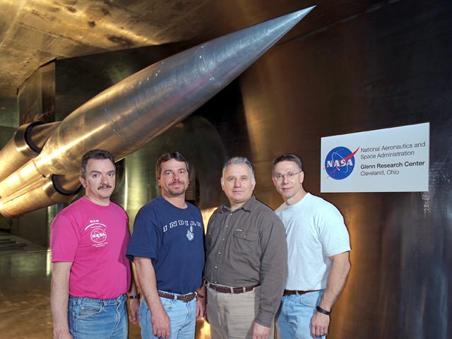
The Unitary Plan Act, passed by Congress in 1949, was a coordinated national plan of facility construction that encompassed the National Advisory Committee for Aeronautics (NACA), Air Force, industry, and universities. In 1956, under the leadership of Dr. Abe Silverstein and Eugene Wasliewski, the 10×10 was brought on line. Dr. Silverstein was responsible for the Mercury program, and for all unmanned satellite programs for the first three years of the agency. He named the Apollo program and laid the groundwork for that program’s success in landing a man on the Moon.
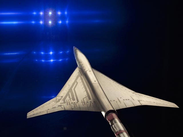
Throughout its history, the tunnel has made valuable contributions to the advancement of fundamental supersonic propulsion technology, the development of Atlas-Centaur, Saturn and Atlas-Agena class launch vehicles, and vehicle-focused research programs including the High-Speed Civil Transport, the National Aerospace Plane, and the Joint Strike Fighter.
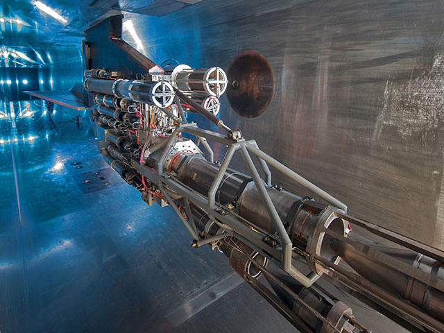
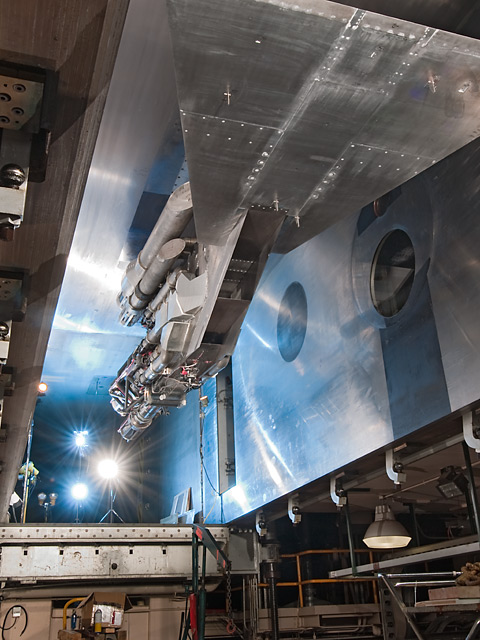
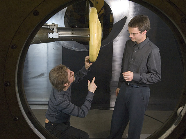
The test section is 10 ft high by 10 ft wide by 40 ft long and can accommodate large-scale models, full-scale engines and aircraft components. The 10×10 was specifically designed to test supersonic propulsion components such as inlets and nozzles, propulsion system integration, and full-scale jet and rocket engines. It can operate as a closed-loop system (aerodynamic cycle) or open-loop system (propulsion cycle), reaching test section speeds of Mach 2.0 to 3.5 and very low speeds from 0 to Mach 0.36. Gust and Mach plates are sometimes installed to expand local Mach number conditions between Mach 1.5 and 4.1. There is also continuous operation across the entire speed and altitude regime, offering users greater flexibility and productivity during testing.

In the propulsion cycle, the tunnel operates by continuously drawing outside air through a very large air dryer to remove the moisture and exhausting it back into the outside environment. This mode is used for models that introduce contaminants into the air stream or use potentially explosive gas mixtures or when the tunnel air-heater is used to simulate flight temperatures. During the aerodynamic cycle, the tunnel runs as a variable density facility that can simulate pressure altitude conditions ranging from 50,000 to 154,000 feet. Dry air is added to maintain test conditions.
The facility is controlled and operated by a digital distributed control system in order to maximize data quality while minimizing operational costs. Steady state and dynamic data is collected from the model instrumentation, processed, and displayed in engineering units and graphical formats. An optical instrumentation suite of capabilities is also used depending on test requirements. To increase test productivity, a test matrix sequencer automatically changes model variables by using a pre-programmed test matrix. Real time transmission and display of all test data and information can be provided to customer locations outside of NASA Glenn.
Specialized support systems and equipment include:
- Tunnel air heater
- Schlieren and advanced optical imagery (infrared, sheet lasers, LDV-Laser Doppler Velocimetry, PSP-Pressure Sensitive Paint, TSP-Temperature Sensitive Paint)
- High-pressure air
- Altitude exhaust
- Cooling water
- Hydraulics
- Gust/Mach plates
- Liquid and gaseous fuel supplies
- Model sting/struts and adapters
- Variety of available research test hardware
For further technical information about the facility, please refer to the capabilities page within this site.
Quick Facts
| Test section: | 10 ft high by 10 ft wide by 40 ft long |
|---|---|
| Mach number: | 0 – 0.36 and 2.0 – 3.5 |
| Altitude (supersonic operation): | 50,000 – 154,000 ft (aerodynamic cycle)
57,000 – 77,000 ft (propulsion cycle) |
| Reynolds no./ft (supersonic operation): | 0.1 to 3.4 x 10⁶ (aerodynamic cycle)
2.2 to 2.7 x 10⁶ (propulsion cycle) |
| Dynamic pressure: | 20-720 psf (aerodynamic cycle
500-600 psf (propulsion cycle) |
| Total temperature: | 540°R-750°R (aerodynamic cycle)
520°R-1140°R (propulsion cycle) |
- When coupled with NASA Glenn’s 8- by 8-Foot Supersonic Wind Tunnel (8×6), the 10×10 provides aerodynamic and propulsion test capabilities from low subsonic through high supersonic Mach range.
- The 10×10 facility is the largest and fastest wind tunnel at NASA Glenn.
- The 10×10 is specifically designed to test supersonic propulsion components such as inlets and nozzles, propulsion system integration, and full-scale jet and rocket engines.
- The 10×10 is equipped to accommodate large-scale aerodynamic (force and moment) models and full-scale engine and aircraft components.
Capabilities
The 10×10 can be run in aerodynamic (closed-loop) cycle or propulsion (open-loop) cycle. It can also run at subsonic test conditions in aerodynamic and propulsion cycles. Subsonic test conditions range from 5 to 240 knots (Mach 0.36) and altitudes up to 50,000 feet.
| Aerodynamic Cycle | Propulsion Cycle | |
|---|---|---|
| Test section |
10 ft high by 10 ft wide by 40 ft long |
|
| Mach no. |
0 – 0.36 and 2.0 – 3.5 |
|
| Altitude (supersonic operation) | 50,000 – 154,000 ft (Mach 2.0 – 3.5)
Up to 50,000 ft (Mach 0 – 0.36) |
57,000 – 77,000 ft (Mach 2.0 – 3.5)
Up to 50,000 ft (Mach 0 – 0.36) |
| Reynolds no./ft (supersonic operation): |
0.1 to 3.4 x 10⁶ | 2.2 to 2.7 x 10⁶ |
| Dynamic pressure | 20 – 720 psf | 500 – 600 psf |
| Total temperature | 540°R – 750°R | 520°R – 1140°R |
Tunnel Support Systems
- High Pressure Air
- High-pressure air (2600 psig) storage: 981,000 scf
- Combustion air: 450 psig at 12 lbm/s (300°F max. temp)
- Service air: 125 psig at 2 lbm/s
- Hydraulics
- Model hydraulics: 3,000 psig at 75 gpm
- Fuels
- Gaseous hydrogen: 1,200 psig at 2 lbm/s
- Gaseous oxygen: 1,500 psig at 23 lbm/s
- Liquid jet fuel: 40 psig 70 gpm
- Vacuum/Exhaust
- Model exhaust: 20 lbm/s (2 lines at 10 lbm/s)
Model Support Systems
- Lower strut assembly: angle of attack range between
-6.0° and 19.0°, height translation - Upper strut assembly: angle of attack range between
-5.0° and 15.0° - Gust Plates: Extends local conditions down to Mach 1.5 or up to Mach 4.1
Data Acquisition
- Steady State Acquisition
- An Escort, steady state data acquisition system, uses an Alpha microprocessor to provide:
- X-Windows based displays
- Real time acquisition and display of engineering unit converted data as well as the resultant calculations
- Computed performance calculations, which can be displayed in a variety of tabular and graphical formats
- Custom tabular display pages
- Scrolling plots
- X-Y plots
- Bargraph plots
- Contour plots
- Growing plots
- Selectable limit checking with inverse video and alarming
- 1-s update rate
- Custom, application-specific features are available upon request
- An Escort, steady state data acquisition system, uses an Alpha microprocessor to provide:
- Salient characteristics specific to the 10×10 SWT data acquisition system are:
- Analog data acquisition with the following accuracies:
- Neff 600 is ± 0.02% of range + 2µv (192 channels)
- Neff 400 is ± 0.05% of range (64 channels)
- Up to 256 Escort Neff channels
- Type K thermocouples (72 Upper Strut, 48 Lower Strut)
- Type J thermocouples (24 Upper or Lower Strut)
- Type T thermocouples (24 Upper or Lower Strut)
- Type R thermocouples (24 Upper Strut)
- Off-site access to data
- Other configurations and system expansion are available upon request.
- Analog data acquisition with the following accuracies:
- Escort pressure data is acquired through Electronically Scanned Pressure (ESP) scanners. The baseline system consists of 32-port, rack mounted scanners with ranges from ±15 psid to ±30 psid, located outside the test section. These scanners are maintained at a constant temperature to extend calibrations intervals up to two hours. Digital Temperature Compensated (DTC) 32-port miniature scanners are also available for use within models.
- Overall accuracies of ±0.05% of range are achieved and confirmed with a check pressure that is applied to the first port of every scanner. This check pressure is also measured by a highly accurate, independent transducer to alarm any deviations with the pressure scanners.
- Typically, 384 to 512 pressure ports are utilized per test. For most tunnel conditions, ±15 psid scanners are sufficient to cover the entire pressure range. For some conditions, ±30 psid scanners are needed for measuring total pressures. System expansion to 1024 pressures is available upon request.
- Transient Data Acquisition
- The Dewetron transient data system provides multi-channel high speed digitized acquisition of rapidly changing cyclic or non-periodic impulse type events. The system consists of:
- 63 channels (expandable upon request) with 24-bit sigma-delta A/Ds per channel
- Data rates from 1,000 to 200,000 samples/ second
- Real time displays
- Tabular (Actual, Average, AC RMS, Pk-Pk, Min, Max )
- Scope
- FFT, PSD
- Strip Chart
- Others
- Near real-time data transfer to customers in standard or custom formats
- Multiple, independent display capability
- Derived “math” channels can be calculated, displayed and stored along with analog data
- The DeweSoft software can be loaded onto a customer’s Windows machine at no cost to be utilized for quick data analysis
- The Dewetron transient data system provides multi-channel high speed digitized acquisition of rapidly changing cyclic or non-periodic impulse type events. The system consists of:
- Flow Visualization
- Pressure sensitive paint
- Both conventional and focused Schlerien systems
- Sheet laser
- Oil flow visualization
- High speed video – up to 1000 full screen frames per second
- Particle Image Velocimetry (PIV)
- Test Article Controls
- Digital model control system with graphical interface
- Automated test article sequencing system
- Remote Access Control Room
- Real-time remote access to all data
- Secure network connections provided
Contact
10- by 10-Foot Supersonic Wind Tunnel (10×10)
Facility Manager: Jonathan Kubiak
216-433-8347
Jonathan.M.Kubiak@nasa.gov
Test Facility Management Branch
Branch Chief: Michael S. McVetta
216-433-2832
michael.s.mcvetta@nasa.gov
Using Our Facilities
NASA’s Glenn Research Center provides ground test facilities to industry, government, and academia. If you are considering testing in one of our facilities or would like further information about a specific facility or capability, please let us know.
Did you test in one of our facilities? Let us know about your experience by participating in our customer facility evaluation survey.
Gallery